


Chapter 2 Hardware Installation and Service 2-21
2.3.6.2 Installing a DDR2 DIMM
The following procedure provides a general guide for installing additional memory.
However, for specific directions on installing DIMMs on the Sun Netra CP3220 blade
server, refer to the documentation that shipped with the DIMMs.
1. Access the blade server by performing one of the following procedures:
■ If the Sun Netra CP3220 blade server is installed in an ATCA shelf, remove the
blade server from the shelf as explained in Section 2.3.3, “Removing the Sun
Netra CP3220 Blade Server” on page 2-18.
■ Remove the Sun Netra CP3220 blade server from its antistatic envelope and place
it on an ESD mat near the ATCA shelf.
2. Take antistatic precautions: Attach and electrically ground the wrist strap.
Caution – Always wear a grounded antistatic wrist strap when handling DIMMs.
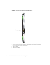
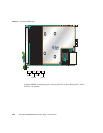
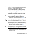
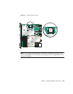
3. Locate the DIMM connectors on the Sun Netra CP3220 blade server.
Select the connectors where you will install the DIMM. See
FIGURE 2-4 for DIMM
slot locations.
Caution – Do not remove the DIMM from its antistatic container until you are
ready to install the DIMM on the Sun Netra CP3220 blade server. Handle the DIMM
only by its edges. Do not touch DIMM components or metal parts. Always wear a
grounded antistatic wrist strap when handling DIMM.
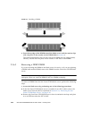
4. Remove the DIMM from its protective packaging, holding the module only by
the edges.
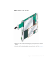
5. Holding the DIMM upright to the blade server, insert the bottom edge of the
DIMM into the bottom of the slot’s hinge-style connector (
FIGURE 2-5).
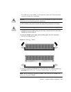
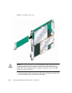
Caution – Evenly engage the DIMM in its hinge-style slot; uneven contact can
cause shorts that will damage the Sun Netra CP3220 blade server. Do not rock the
DIMM into place. Ensure that all contacts engage at the same time. You will feel or
hear a click when the DIMM properly seats in the connector.
The socket and module are both keyed, which means that the DIMM can be
installed only one way. With even pressure, push simultaneously on both upper
corners of the DIMM until its bottom edge (the edge with the gold fingers) is
firmly seated in the connector.