4 Replacement Procedures 4.11 BASE ASSY
4.11 BASE ASSY
Removing the BASE ASSY
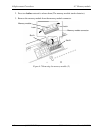
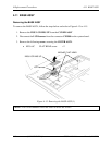
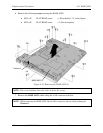
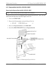
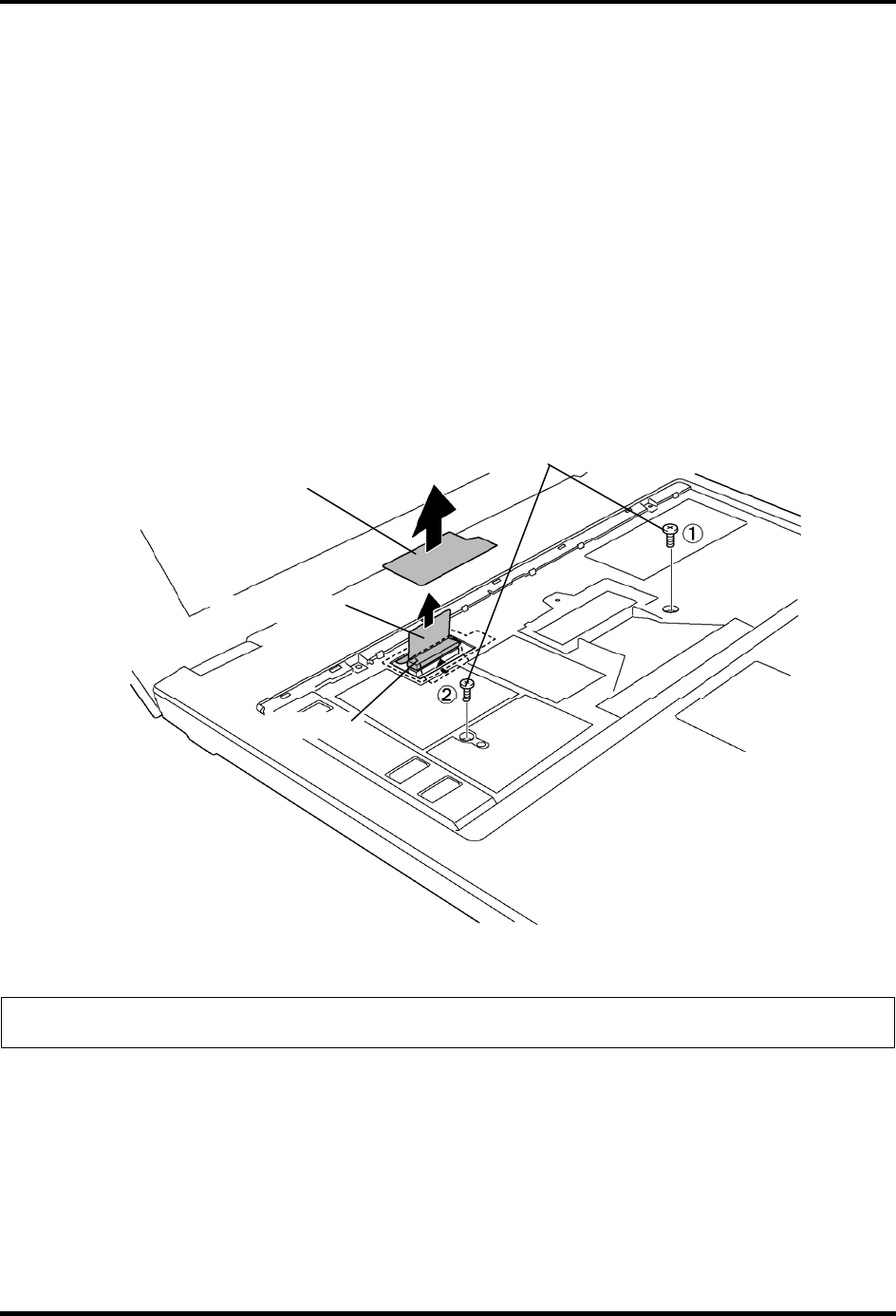
To remove the BASE ASSY, follow the steps below and refer to Figure 4-13 to 4-15.
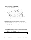
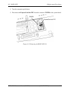
1. Remove the INSU LCD HNS UP from the COVER ASSY
2. Disconnect the LCD harness from the connector CN5000 on the system board.
3. Remove the following screws securing the COVER ASSY.
• M2.5×6C FLAT HEAD screw ×2
M2.5x6C FLAT HEAD
CN5000
LCD harness
INSU LCD HNS UP
Figure 4-13 Removing the BASE ASSY (1)
NOTE: The circled number shows the order to drive the screws.
4-26 [CONFIDENTIAL] TECRA R10 Maintenance Manual (960-708)


