4 Replacement Procedures 4.11 BASE ASSY
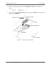
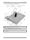
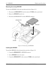
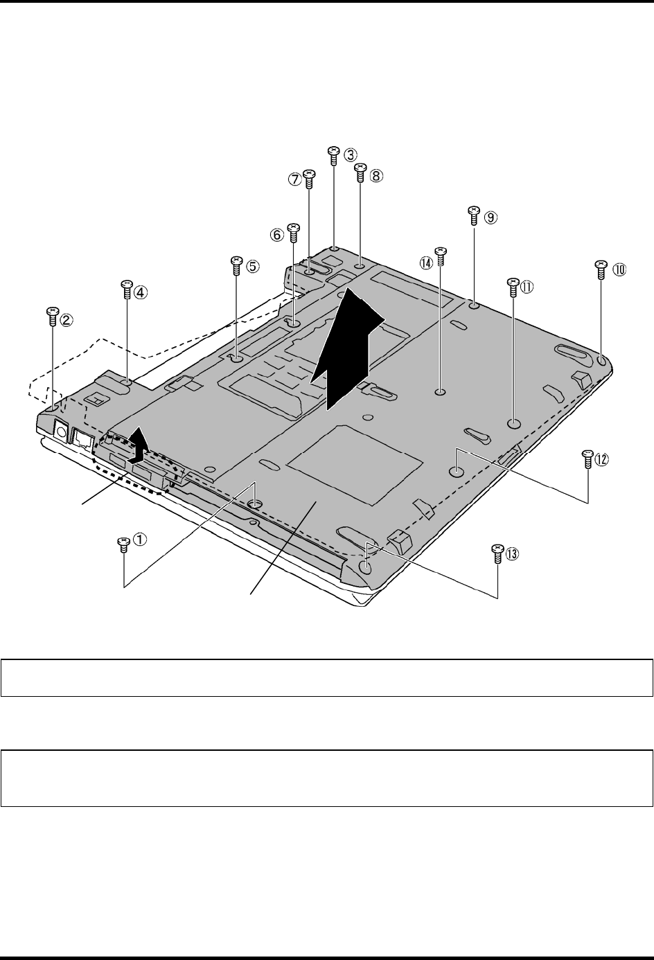
6. Remove the following screws securing the BASE ASSY.
• M2.5×4C FLAT HEAD screw ×1 (Described as “A” in the figure)
• M2.5×6C FLAT HEAD screw ×13 (No description)
BASE ASSY
(A)
Portion A
Figure 4-15 Removing the BASE ASSY (3)
NOTE: The circled number shows the order to drive the screws.
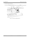
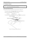
7. Remove the BASE ASSY while lifting the LAN connector side first.
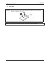
NOTE: When removing the BASE ASSY, lift the LAN connector side up while pushing the
Portion A.
4-28 [CONFIDENTIAL] TECRA R10 Maintenance Manual (960-708)


