


4.16 DC-IN HARNESS/RJ45 WIRE HARNESS 4 Replacement Procedures
TECRA R10 Maintenance Manual (960-708) [CONFIDENTIAL] 4-41
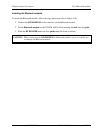
Installing the DC-IN HARNESS/RJ45 WIRE HARNESS
To install the DC-IN HARNESS/RJ45 WIRE HARNESS, follow the steps below and refer to
Figure 4-21 to 4-23.
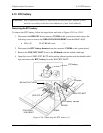
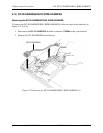
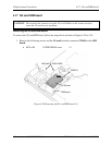
1. Set the RJ45 WIRE HARNESS into the HARNESS HOLDER R.
2. Set the HARNESS HOLDER R in the slot in place and secure it with following screws.
• M2.5×6C FLAT HEAD screw ×1
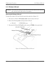
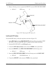
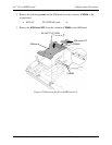
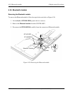
3. Arrange the 3G antenna cables, Wireless LAN antenna cables, RJ45 WIRE
HARNESS and CAMERA HARNESS on the HARNESS HOLDER R.
4. Connect the two 3G antenna cables to the terminals on the 3G card, RJ45 WIRE
HARNESS to the connector CN4100 on the system board and CAMERA HARNESS to
the connector CN9540 on the system board.
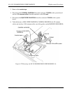
5. Stick the acetate tape in place.
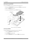
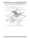
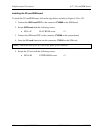
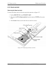
6. Set the DC-IN HARNESS in the slot in place and connect the DC-IN HARNESS to the
connector CN8800 on the system board.