


4.11 BASE ASSY 4 Replacement Procedures
TECRA R10 Maintenance Manual (960-708) [CONFIDENTIAL] 4-29
Installing the BASE ASSY
To install the BASE ASSY, follow the steps below and refer to Figure 4-13 to 4-15.
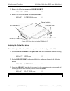
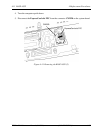
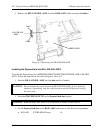
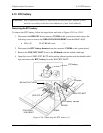
1. Set the BASE ASSY in place while setting the RGB connector side first. (See figure 4-
15).
2. Secure the BASE ASSY with the following screws.
• M2.5×6C FLAT HEAD screw ×13 (No description)
• M2.5×4C FLAT HEAD screw ×1 (Described as “A” in the figure)
CAUTION: Drive the fourteen screws in the order shown in the Figure 4-15.
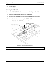
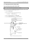
3. Connect the ExpressCard slot FPC to the connector CN2520 on the system board.
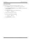
4. Turn the computer upside down.
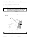
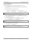
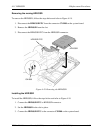
5. Connect the LCD harness to the connector CN5000 on the system board.
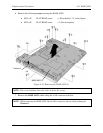
6. Stick the INSU LCD HNS UP on the COVER ASSY in place.
CAUTION: Do not reuse the removed INSU LCD HNS UP. Use a new one.
7. Secure the BASE ASSY with following screws.
• M2.5×6C FLAT HEAD screw ×2
CAUTION: Drive the two screws in the order shown in the Figure 4-13.