


TM-XDOP-01XN xxi
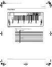
Figure 1-1 Front Panel (6000 Watt) - - - - - - - - - - - - - - - - - - - - - - - - - - - - - - - - - - - - - 1–3
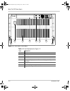
Figure 1-2 Front Panel (12000 Watt) - - - - - - - - - - - - - - - - - - - - - - - - - - - - - - - - - - - - 1–4
Figure 1-3 Keypad - - - - - - - - - - - - - - - - - - - - - - - - - - - - - - - - - - - - - - - - - - - - - - - - 1–5
Figure 1-4 Front Panel Display - - - - - - - - - - - - - - - - - - - - - - - - - - - - - - - - - - - - - - - - 1–9
Figure 1-5 Front Panel Display, Status Annunciators - - - - - - - - - - - - - - - - - - - - - - - - - 1–9
Figure 1-6 Rear Panel (6000 Watt) - - - - - - - - - - - - - - - - - - - - - - - - - - - - - - - - - - - - 1–11
Figure 2-1 Typical Box Label for Storage- - - - - - - - - - - - - - - - - - - - - - - - - - - - - - - - - 2–3
Figure 2-2 Unpacking the Power Supply- - - - - - - - - - - - - - - - - - - - - - - - - - - - - - - - - - 2–5
Figure 2-3 Mounting the Power Supply in the Rack With Support Rails - - - - - - - - - - - - 2–6
Figure 2-4 AC Input Connector for 6000 Watt units - - - - - - - - - - - - - - - - - - - - - - - - - - 2–7
Figure 2-5 Attaching the AC Input Wires for 6000 Watt units - - - - - - - - - - - - - - - - - - 2–10
Figure 2-6 Attaching the AC Input Wires for 12000 Watt units - - - - - - - - - - - - - - - - - 2–12
Figure 2-7 Fastening the Output Wires (6000 Watt) - - - - - - - - - - - - - - - - - - - - - - - - - 2–19
Figure 2-8 Output Bus Bar Cover for 6000 Watt units - - - - - - - - - - - - - - - - - - - - - - - 2–20
Figure 2-9 Output for 12000 Watt units - - - - - - - - - - - - - - - - - - - - - - - - - - - - - - - - - 2–21
Figure 2-10 Output Cover with Strain Relief for 6000 Watt units - - - - - - - - - - - - - - - - - 2–22
Figure 2-11 Output for 12000 Watt units - - - - - - - - - - - - - - - - - - - - - - - - - - - - - - - - - 2–23
Figure 4-1 View of Remote Interface Connections - - - - - - - - - - - - - - - - - - - - - - - - - - - 4–3
Figure 4-2 Schematic For User Line Interface - - - - - - - - - - - - - - - - - - - - - - - - - - - - - - 4–6
Figure 4-3 Connections for Multichannel Operation - - - - - - - - - - - - - - - - - - - - - - - - - 4–13
Figure 4-4 Operation Status Registers - - - - - - - - - - - - - - - - - - - - - - - - - - - - - - - - - - 4–45
Figure 4-5 Questionable Status Registers - - - - - - - - - - - - - - - - - - - - - - - - - - - - - - - - 4–51
Figure 4-6 IEEE 488.2 Status Register and Status Byte- - - - - - - - - - - - - - - - - - - - - - - 4–54
Figure 5-1 Connections for Current Share Operation - - - - - - - - - - - - - - - - - - - - - - - - - 5–2
Figure A-1 Power Supply Dimensions (6000 Watt unit)- - - - - - - - - - - - - - - - - - - - - - - A–14
Figure A-2 Power Supply Dimensions (12000 Watt unit)- - - - - - - - - - - - - - - - - - - - - - A–15
Figures
TM-XDOP-01XN.book Page xxi Monday, July 17, 2006 11:19 AM