


Installation
2–2 TM-XDOP-01XN
Overview
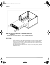
Chapter 2, “Installation” provides recommendations and procedures for
inspecting, installing, and testing the power supply. For more information about
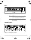
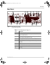
controls and connectors, refer to the front panel diagrams (Figure 1-1 to Figure 1-
5) as well as the rear panel diagram (Figure 1-6) in Chapter 1.
Basic Setup Procedure
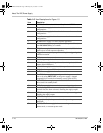
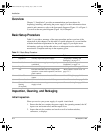
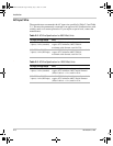
Table 2-1 provides a summary of the setup procedure and an overview of the
subsections in this chapter. Use this table as a quick reference if you are familiar
with the installation requirements for the power supply. If you require more
information, each step in the table refers to a subsequent section which contains
more details. Complete each step in the sequence given.
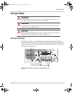
Inspection, Cleaning, and Packaging
Initial Inspection
When you receive your power supply, do a quick visual check.
1. Ensure that the box contains the power supply, the operating manual, the AC
input cover and strain relief, and the output cover.
2. Inspect the unit for scratches and cracks as well as broken switches,
connectors, or displays.
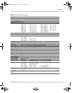
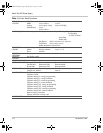
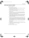
Table 2-1
Basic Setup Procedure
Step # Description Action Reference
1 Inspection Visually inspect the power supply. “Inspection, Cleaning, and
Packaging” on page 2–2
2 Installation Install the power supply, ensuring adequate
ventilation.
“Location, Mounting, and
Ventilation” on page 2–4
3 Input Power Connect AC input power. “AC Input Power” on page 2–7
4 Test Perform functional tests for voltage mode
operation, current mode operation, and front
panel controls.
“Basic Checks or Self-Tests” on
page 2–13
5 Select Wires Select wires that can tolerate the DC current
output.
“Load Wiring” on page 2–16
6 Connect Load Connect the load wires to the DC output. “Load Connections” on page 2–18
7 Connect Remote
Sensing
(if required)
Connect remote sensing connectors on power
supply to load.
“Remote Sensing” on page 2–24
TM-XDOP-01XN.book Page 2 Monday, July 17, 2006 11:19 AM