


SETTING THE SYSTEM CONFIGURATION
4-48 XEROX DOCUPRINT 4050/4090 IPS GUIDE TO CONFIGURING AND MANAGING THE SYSTEM
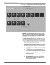
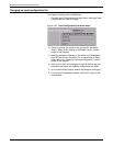
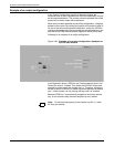
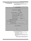
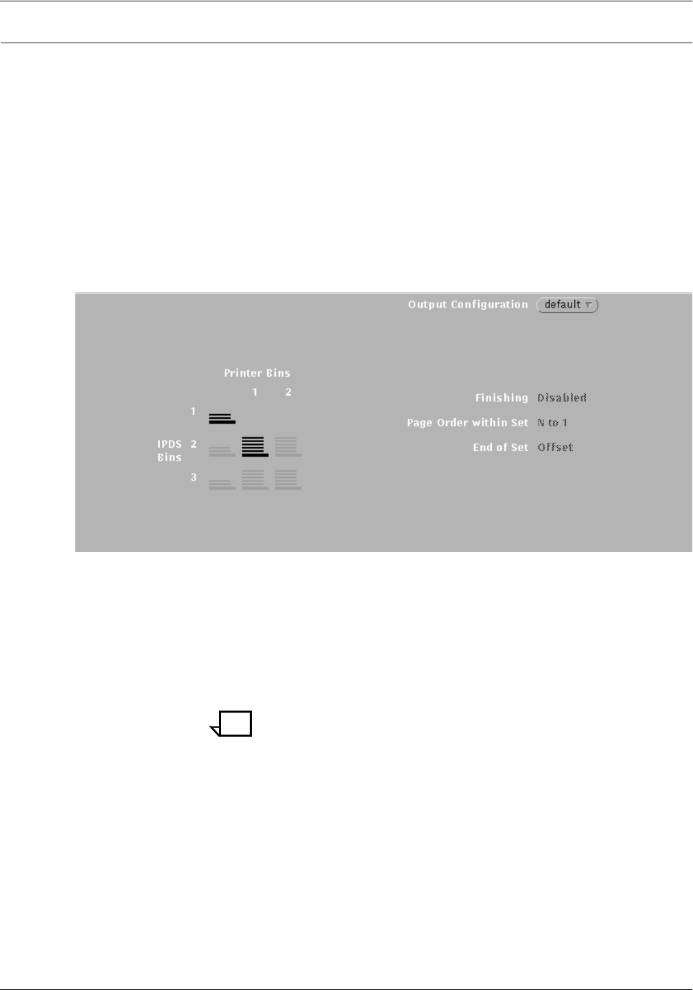
Example of an output configuration
In the Output Configuration section of the main window, the
horizontal rows of icons represent the IPDS bins specified in the job
as the output destination. The vertical columns represent the actual
printer bins to which output will be delivered.
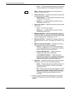
When a bin has been selected as part of the configuration, it displays
bolded on the screen. By looking at the printer bin number or letter at
the top of the column above each bolded icon, and at the IPDS bin
number at the beginning of the row beside the same bolded icon, you
can see which IPDS bins have been mapped to which printer bins.
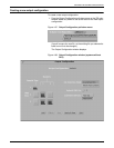
Following is an example of an output configuration.
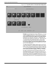
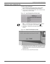
Figure 4-36. Example of an output configuration, displayed on
the IPS main window
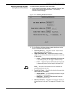
In the illustration above, IPDS bin row 2 has the stacker icon in the
Printer Bin column 1 bolded. This shows that IPDS bin 2 has been
mapped to printer output bin (stacker tray) 1. Therefore, all parts of
the job for which IPDS bin 2 is called out will be delivered to stacker
tray 1. When stacker 1is full, printing will stop until it is emptied.
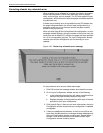
Because IPDS bin 1 is permanently mapped to the printer sample
tray, its row contains only the short sample tray icon, bolded.
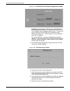
Note: To avoid all output going to the sample tray (bin 1), make
bin 2 as your default.