


INTERFACES
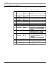
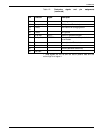
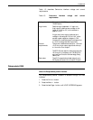
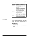
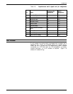
Table 1-5. Dataproducts voltage and current requirements
Voltage levels 0 (zero) and +5 VDC (nominal), TTl (SN
74LS00 series
Logic levels Positive logic is assumed. A logic one (or
high) signal is defined as a voltage in the
range of +2.4V to +5V, not to exceed a
peak of +5.5V.
A logic zero (or low) signal is defined as a
voltage in the range of 0.0V to 0.4V, not to
exceed a peak negative voltage of -0.5V.
However for received signals a voltage of up
to +0.8V is recognised as a logic zero.
Current
requirements
The printer interface sources up to -15 ma at
+2.4V for a high output signal and sinks up
to 14 ma for a low output.
74LS374 ICs are used for data receivers with
a 220 ohm pull-up resistors, and a 330 ohm
pull-down resistor. 74LS244 ICs are used as
drivers and for Ready, On-line and Demand.
Data rates The 4213 supports burst data rates of up to
50 Kbytes per second for at least 560 bytes,
or until a line-end or form-feed is detected.
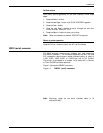
Serial interface
The serial interface, as well as the serial interface features
supported by the 4213, are selected through the User Interface.
The serial interface connector is compatible with RS232-C DTE
standards.
Select the serial interface
1. Press the Online H button.
2. Press the Menu A button.
3. Press the Last Page C button until HOST INTERFACE
appears.
XEROX 4213 LASER PRINTER PROGRAMMER REFERENCE 1-11