


ES-2024 Series User’s Guide
Chapter 3 Hardware Overview 46
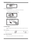
To connect the power to the switch, insert the female end of power cord to the power
receptacle on the rear panel. Connect the other end of the supplied power cord to the power
source.
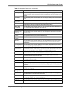
3.3 LEDs
The LEDs are located on the front panel. The following table describes the LEDs on the front
panel.
Table 2 LEDs
LED COLOR STATUS DESCRIPTION
PWR Green On The system is turned on.
Off The system is off.
SYS Green Blinking The system is rebooting and performing self-diagnostic tests.
On The system is on and functioning properly.
Off The power is off or the system is not ready/malfunctioning.
ALM Red On There is a hardware failure.
Off The system is functioning normally.
Ethernet Ports
LNK/ACT Green Blinking The system is transmitting/receiving to/from a 10 Mbps Ethernet
network.
On The link to a 10 Mbps Ethernet network is up.
Amber Blinking The system is transmitting/receiving to/from a 100 Mbps Ethernet
network.
On The link to a 100 Mbps Ethernet network is up.
Off The link to an Ethernet network is down.
FDX/COL Amber Blinking The Ethernet port is negotiating in half-duplex mode and collisions
are occurring; the more collisions that occur the faster the LED
blinks.
On The Ethernet port is negotiating in full-duplex mode.
Off The Ethernet port is negotiating in half-duplex mode and no
collisions are occurring.
POE Amber On Power is supplied to the port.
Off Power is not supplied to the port.
Gigabit Ports
100/1000 Green On The link to a 1000 Mbps Ethernet network is up.
Amber On The link to a 100 Mbps Ethernet network is up.
Off The link to an Ethernet network is down.
ACT Green Blinking The port is receiving or transmitting data.
On The port has a connection to an Ethernet network but not
receiving or transmitting data.
Off The link to an Ethernet network is down.