


64 CHAPTER 9: TROUBLESHOOTING
2 Connect a straight-through cable from the PC to the hub.
The hub performs an internal crossover so that the signal can go from TD+ to RD+
and TD– to RD–. When you look at an RJ-45 connector from the front (that is, the
opposite side from where the wires enter the connector), pin 1 is identified on the
right side when the metal contacts are facing up.
3 Make sure that the TD+ and TD– wires are twisted together, and that the RD+ and
RD– are twisted together.
Using wires from opposing pairs can cause signals to be lost.
Troubleshooting Hubs A crossover cable can be used to identify the type of failure when hub
performance or connectivity is in question.
To use a crossover cable:
1 Connect a file server and a client PC back-to-back with a crossover cable to verify
that the NIC and network operating system are properly configured.
2 To make a crossover cable, connect TD+ to RD+ and TD– to RD–.
The cable performs the crossover that is usually performed by the hub.
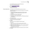
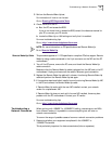
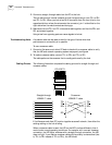
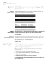
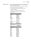
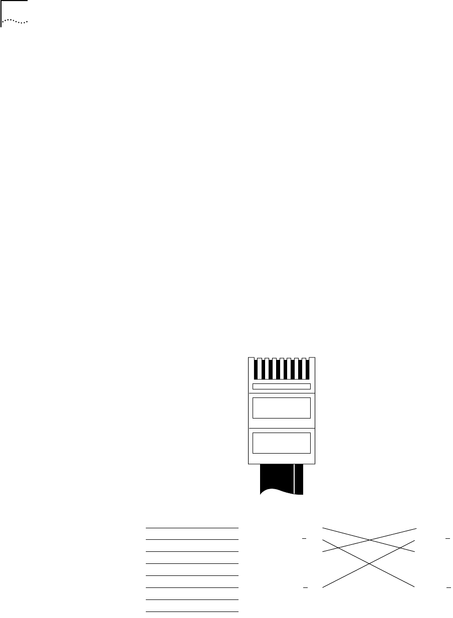
Cabling Pinouts The following illustration compares the cabling pinouts for straight-through and
crossover cables.
If the file server and client PC function together as a small network, then either the
existing cabling or the hub is failing.
When a crossover cable is used, the LED on the NIC functions differently than it
would under normal operating conditions. For example, with a correct crossover
connection, the LED lights, whereas with a straight-through connection, the LED
does not light. If you make a crossover cable and the polarity is mismatched (that
is, TD+ to RD– instead of TD+ to RD+), the LED blinks.
1
2
3
4
5
6
7
8
1
2
3
4
5
6
7
8
1
2
3
4
5
6
7
8
1
2
3
4
5
6
7
8
Straight-through
10BASE-T cable
Crossover
10BASE-T cable
12345678
TD+
RD+
TD
RD
TD+
RD+
TD
RD