


B-5
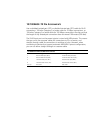
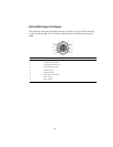
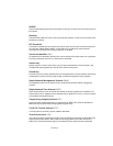
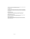
8-PIN DIN CONNECTOR PINOUT
The Ethernet cable from the power injector connects to an 8-pin DIN connector
on the wireless bridge. This connector is described in the following figure and
table.
8-Pin DIN Ethernet Port Pinout
Pin Signal Name
1 Transmit Data plus (TD+)
2 Transmit Data minus (TD-)
3 Receive Data plus (RD+)
4 +48 VDC power
5 +48 VDC power
6 Receive Data minus (RD-)
7 Return power
8 Return power
Note: The “+” and “-” signs represent the polarity of the wires that make up each wire pair.
1
7
2
3
4
5
8
6