


ADCP-96-015 • Issue 1 • July 2004
Page 14
© 2004, ADC Telecommunications, Inc.
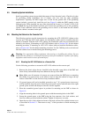
10. Feed each distribution cable into the appropriate conduit section and route to the splice
enclosure (not provided). Any excess cable slack may be stored in the bottom of the FMS.
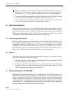
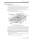
11. Lower the cabinet onto the ground spacer or adapter cover and align the mounting holes in
the bottom of the cabinet with the holes in the cover.
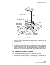
12. If the installation includes a ground spacer, secure the cabinet to the spacer using the four
hex bolts, four flat washers and four nuts provided with the spacer. If the installation does
not include a ground spacer, secure the cabinet to the adapter cover using the four
capscrews, four lock washers, and four flat washers provided with the cabinet. Tighten all
fasteners securely.
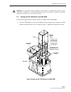
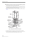
13. Install the FMS sleeve cover onto the FMS and secure using the two capscrews and
washers provided with the cover. Tighten both capscrews securely.
Note: A separate splice enclosure (not provided) is required for splicing the cabinet OSP
distribution cables to the system OSP distribution cables. If preferred, the splice enclosure
for the distribution cables may be mounted within the FMS-20000.