


ADCP-96-015 • Issue 1 • July 2004
Page 2
© 2004, ADC Telecommunications, Inc.
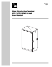
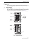
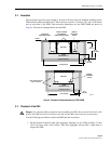
The outside plant (OSP) feeder and distribution cables enter the cabinet from the bottom rear
side. Clamps are provided for securing each cable to the inside of the cabinet. The bottom of the
cabinet is enclosed with a two-piece removable moisture barrier. The cable entry/exit holes are
fitted with grommets to resist the entry of dust and moisture. On an optional basis, the cabinet
may be ordered with the distribution cables pre-installed.
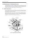
The ACE-142S/142V cabinet is constructed of heavy gauge aluminum and is coated with an
almond-colored finish. The cabinet doors are equipped with tamper-resistant latches with hasps
for padlocks, stainless steel hinges, and door catches to prevent accidental closing. Access to the
cabinet requires a
216B key tool (accessory) to operate the latches. Lifting eyes are attached to
the sides of the cabinet to allow use of hoisting equipment. A grounding bus is provided within
the cabinet for grounding the cabinet and cables per local practice.
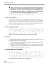
The ACE-142S/142V cabinet can accommodate up to thirty-seven round splice trays, up to
twelve 1x8 or 1x32 splitter modules, and five 72-position connector panels equipped with APC/
SC adapters. Seven splice tray slots are provided for feeder cable splices. Thirty splice tray slots
are provided for distribution cable splices. The ACE-142S/142V cabinet is equipped with two
doors that provide front and rear access to the optical components. The specifications for the
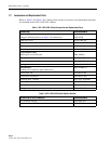
ACE-142S/142V cabinet are provided in Table 1.
Table 1. ACE-142S/142V Cabinet Specifications
PARAMETER SPECIFICATION
Cabinet
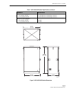
Dimensions (W x D x H) – See Figure 2 27.5 x 19.7 x 47.5 inches (699 x 500.4 x 1206.5 mm)
Weight (fully loaded) 210 lbs (95.3 kg)
Certification (Pending) GR-2898-CORE (Issue 2, December 1999)
Distribution ports 360 (with 5 connector panels installed)
Distribution port connectors APC/SC
Splitter module capacity (1x8 or 1x32) 12
Splice tray capacity (round)
Feeder cable
Distribution cable
7
30
Total feeder cable splices 84 (7 splice trays with 12 splices per tray)
Total distribution cable splices 360 (30 splice trays with 12 splices per tray)
Splitter Modules
Splitter module output pigtails 2 mm with APC/SC connectors
Splitter module input pigtail 2 mm
Test bandpass 1260–1360 nm
1480–1500 nm
1550–1560 nm
Overall bandpass 1260–1625 nm