


ADCP-96-015 • Issue 1 • July 2004
Page 33
© 2004, ADC Telecommunications, Inc.
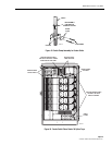
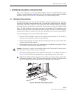
7. Slide the bottom cover down to the bottom of the cabinet.
8. Align the five holes in the bottom cover with the five studs around the edge of the cabinet.
9. Install a flat washer and lock nut (removed in step 1 of Section 5.1) on each stud and
tighten securely.
6.3 Distribution Cable and Connector Panel Pigtail Splicing
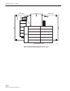
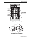
The distribution cable must be spliced to the connector panel pigtails. Up to five 72-port
connector panels may be mounted in the cabinet which requires a maximum of 360 distribution
splices. Round splice trays are used for splicing and six splice tray mounting slots are provided
per panel. This equates to a maximum of 30 spice trays when five connector panels are installed.
Each splice tray can hold up to 12 splices. Use the following procedure to install the distribution
cable fibers and the connector panel pigtails in the splice tray in preparation for splicing:
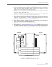
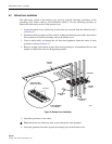
1. Locate splice tray #1 (on the left side) and remove that tray from the cabinet.
2. Uncoil the connector panel pigtail subunit from the splice tray.
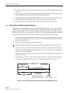
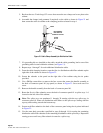
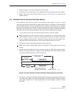
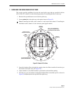
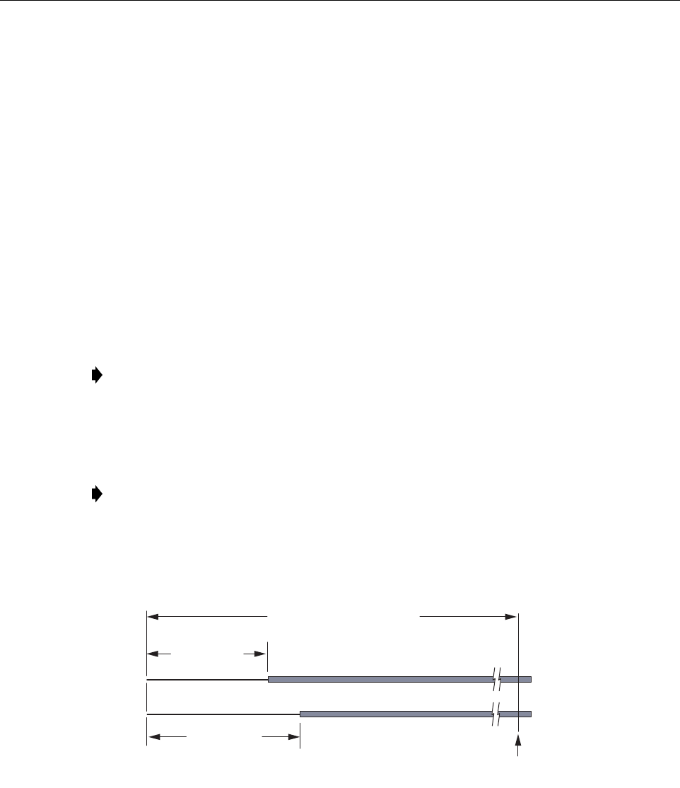
3. Starting at the last column (left side) of tie points on the rear side of the connector panel,
measure and mark the fiber cut lengths for the distribution cable fiber subunits and the
connector panel fiber subunits as shown in Figure 25.
Figure 25. Cut Length and Breakout Length for Distribution Cable and Connector Panel Fibers
4. Cut both the distribution cable fiber subunit and the connector panel pigtail subunit at the
cut length mark. Make sure that the distribution cable fiber subunit and the connector
panel pigtail subunit are of equal length and the overall length is within the range
specified.
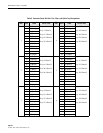
Note: The pigtails from each connector panel are grouped into six 12-fiber subunits. Each
pigtail subunit is routed to a splice tray located on the left side of the cabinet. The splice
trays are numbered consecutively 1 through 30 starting with at the top. The subunit, port,
fiber, and splice tray designations for each connector panel are shown in Table 5.
Note: Each connector panel pigtail subunit is temporarily coiled around a splice tray for
storage.
COMMON
TIE POINT IN CABINET
19276-A
BREAKOUT
LENGTH 48 IN
(122 CM)
BREAKOUT
LENGTH 37 IN
(94 CM)
CUT LENGTH* 68 TO 146 IN
(173 TO 371 CM)
DISTRIBUTION CABLE
FIBER SUBUNIT
CONNECTOR PANEL
FIBER SUBUNIT
*THE CUT LENGTH MUST BE
THE SAME FOR BOTH FIBERS