


ADCP-96-015 • Issue 1 • July 2004
Page 18
© 2004, ADC Telecommunications, Inc.
4.5 Grounding System Installation
Install a grounding system (not provided) that meets all local electrical codes. Check local codes
for grounding system installation, use of clamps, wire size, and any other grounding
requirements. Typically, #6 AWG copper wire is used for the ground wire. If the grounding
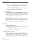
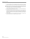
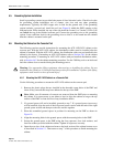
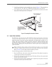
system includes a ground rod, install the rod (see Figure 8) within the PMF opening at the
indicated point. When installed, the top of the rod should be located 1 to 2 inches (2.54 to 5.08
cm) below the top of the finished concrete pad. Connect the grounding wire to the grounding
system. Leave sufficient slack in the grounding wire to allow it to be routed into the cabinet
after the cabinet is mounted on the pad.
4.6 Mounting the Cabinet on the Concrete Pad
The following sections provide instructions for mounting the ACE-142S/142V cabinet on the
concrete pad. With the ACE-142S cabinet, the distribution cables must be installed after the
cabinet is mounted. With the ACE-142V cabinet, the distribution cables are pre-installed in the
cabinet by the factory. If mounting an ACE-142S cabinet, refer to Section 4.6.1 for the cabinet
mounting procedure. If mounting an ACE-142V cabinet with pre-installed distribution cables,
refer to Section 4.6.2 for the cabinet mounting procedure. Use the 216B key tool to un-latch and
latch the cabinet doors as needed during the mounting process.
4.6.1 Mounting the ACE-142S Cabinet on a Concrete Pad
Use the following procedures to mount the ACE-142S cabinet on the concrete pad.
1. Remove the plastic plugs that are installed in the threaded corner holes of the PMF and
clean off any concrete that may have adhered to the top of the PMF.
2. If a ground spacer will not be installed, proceed to step 7. If a ground spacer (accessory)
will be installed, align the ends of the left ground spacer section with the ends of the right
ground spacer section and then press the two sections together.
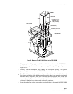
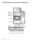
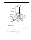
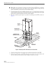
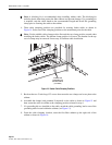
3. Place the assembled ground spacer in position for mounting on the PMF as shown in
Figure 10.
4. Align the mounting holes in the ground spacer with the mounting holes in the PMF.
5. Secure the ground spacer to the PMF using the four capscrews, four lock washers, and
four flat washers provided with the cabinet. Tighten all capscrews securely.
6. Open the rear door of the cabinet and remove the back section of the cabinet bottom cover
as described in Section 5.1. Then return to step 7 of this procedure to finish mounting the
cabinet.
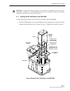
Warning: Use appropriate lifting equipment when moving or installing the cabinet. Do not
stand under the cabinet as it is being hoisted into position for installation. A failure of the lifting
equipment could result in serious personal injury.
Note: Make sure all remnants of concrete are removed from the PMF prior to mounting
the cabinet. It is not necessary to use shims to level or align the cabinet as long as the top
surface of the PMF is clean and free of any installation debris.