


Configuring Multicast Address Boundaries Multicast Address Boundaries Overview
OmniSwitch 6800/6850/9000 Advanced Routing Configuration Guide December 2007 page 5-5
Multicast Address Boundaries
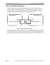
Without multicast address boundaries, multicast traffic conflicts can occur between domains. For exam-
ple, a multicast packet addressed to 239.140.120.10 from a device in one domain could “leak” into another
domain. If the other domain contains a device attempting to send a separate multicast packet with the same
address, a conflict may occur. A boundary is used to eliminate these conflicts by confining multicast traf-
fic on an IP interface. When a boundary is set, multicast packets with a destination address within the
specified boundary will not be forwarded on the interface.
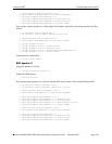
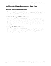
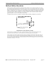
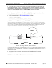
The figure below provides an example of a multicast address boundary configured on an interface.
Simple Multicast Address Boundary Example
An IP interface is configured on VLAN 2, with the IP address 172.22.2.44. The IP interface is also
referred to as the router interface; the IP address serves as the identifier for the interface.
In this example, the multicast address boundary has been defined as 239.140.120.0. The mask value of
255.255.255.0 is shown in Classless Inter-Domain Routing (CIDR) prefix format as /24. This specifies
that no multicast traffic addressed to multicast addresses 239.140.120.0 through 239.140.120.255 will be
forwarded on interface 172.22.2.44.
Multicast Domain 1
Multicast Address Boundary
239.140.120.0/24
239.140.120.x
Multicast Traffic
VLAN 2
Router
Port
172.22.2.44