


Configuring OSPF OSPF Application Example
OmniSwitch 6800/6850/9000 Advanced Routing Configuration Guide December 2007 page 1-37
The commands for this step are below:
Router 1
-> ip ospf area 0.0.0.0
-> ip ospf area 0.0.0.1
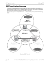
These commands created area 0.0.0.0 (the backbone) and area 0.0.0.1 (the area
for Router 1). Both of these areas are also enabled.
Router 2
-> ip ospf area 0.0.0.0
-> ip ospf area 0.0.0.2
These commands created Area 0.0.0.0 (the backbone) and Area 0.0.0.2 (the area
for Router 2). Both of these areas are also enabled.
Router 3
-> ip ospf area 0.0.0.0
-> ip ospf area 0.0.0.3
These commands created Area 0.0.0.0 (the backbone) and Area 0.0.0.3 (the area
for Router 3). Both of these areas are also enabled.
Step 4: Create, Enable, and Assign Interfaces
Next, OSPF interfaces must be created, enabled, and assigned to the areas. The OSPF interfaces should
have the same interface name as the IP router ports created above in “Step 1: Prepare the Routers” on
page 1-35.
Router 1
-> ip ospf interface vlan-31
-> ip ospf interface vlan-31 area 0.0.0.0
-> ip ospf interface vlan-31 status enable
-> ip ospf interface vlan-12
-> ip ospf interface vlan-12 area 0.0.0.0
-> ip ospf interface vlan-12 status enable
-> ip ospf interface vlan-10
-> ip ospf interface vlan-10 area 0.0.0.1
-> ip ospf interface vlan-10 status enable
IP router port 31.0.0.1 was associated to OSPF interface vlan-31, enabled, and assigned to the backbone.
IP router port 12.0.0.1 was associated to OSPF interface vlan-12, enabled, and assigned to the backbone.
IP router port 10.0.0.1 which connects to end stations and attached network devices, was associated to
OSPF interface vlan-10, enabled, and assigned to Area 0.0.0.1.
Router 2
-> ip ospf interface vlan-12
-> ip ospf interface vlan-12 area 0.0.0.0
-> ip ospf interface vlan-12 status enable
-> ip ospf interface vlan-23
-> ip ospf interface vlan-23 area 0.0.0.0
-> ip ospf interface vlan-23 status enable