


OSPF Application Example Configuring OSPF
page 1-36 OmniSwitch 6800/6850/9000 Advanced Routing Configuration Guide December 2007
-> ip router router-id 2.2.2.2
These commands created VLANs 12, 23, and 20.
• VLAN 12 handles the backbone connection from Router 1 to Router 2, using the IP router port 12.0.0.2
and physical port 2/1.
• VLAN 23 handles the backbone connection from Router 2 to Router 3, using the IP router port 23.0.0.2
and physical port 2/2.
• VLAN 20 handles the device connections to Router 2, using the IP router port 20.0.0.2 and physical
ports 2/3-5. More ports could be added at a later time if necessary.
The router was assigned the Router ID of 2.2.2.2.
Router 3 (using ports 2/1 and 2/2 for the backbone, and ports 2/3-5 for end devices):
-> vlan 23
-> ip interface vlan-23 vlan 23 address 23.0.0.3 mask 255.0.0.0
-> vlan 23 port default 2/1
-> vlan 31
-> ip interface vlan-31 vlan 31 address 31.0.0.3 mask 255.0.0.0
-> vlan 31 port default 2/2
-> vlan 30
-> ip interface vlan-30 vlan 30 address 30.0.0.3 mask 255.0.0.0
-> vlan 30 port default 2/3-5
-> ip router router-id 3.3.3.3
These commands created VLANs 23, 31, and 30.
• VLAN 23 handles the backbone connection from Router 2 to Router 3, using the IP router port 23.0.0.3
and physical port 2/1.
• VLAN 31 handles the backbone connection from Router 3 to Router 1, using the IP router port 31.0.0.3
and physical port 2/2.
• VLAN 30 handles the device connections to Router 3, using the IP router port 30.0.0.3 and physical
ports 2/3-5. More ports could be added at a later time if necessary.
The router was assigned the Router ID of 3.3.3.3.
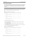
Step 2: Enable OSPF
The next step is to load and enable OSPF on each router. The commands for this step are below (the
commands are the same on each router):
-> ip load ospf
-> ip ospf status enable
Step 3: Create the Areas and Backbone
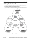
Now the areas should be created. In this case, we will create an area for each router, and a backbone (area
0.0.0.0) that connects the areas.