Chapter 1. Introduction
7
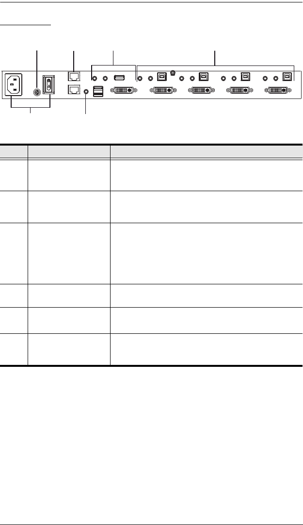
Rear View
No. Component Description
1 Daisy Chain Control
In / Out ports
Use these ports to connect to another CM1164’s DCC
port to pass keyboard and mouse signals. You can
daisy chain up to four CM1164 units.
2 Console Port Section The cables from your USB keyboard, USB mouse, DVI
console display, a USB peripheral, microphone and
speakers plug into this section.
3 DVI KVM Port Section The cables that link the CM1164 to your DVI-D Single
Link computers plug in here. Each DVI KVM port is
comprised of a microphone jack, speaker jack, USB
type B socket, and a DVI Single Link connector.
You can initiate a firmware upgrade from the computer
connected to these ports.
4 Power Socket / Power
Switch
Plug in the power cord to the power socket and use
the switch to power on the CM1164.
5 Grounding Terminal The grounding wire (used to ground the unit) attaches
here.
6IR Receiver
(Extension)
This receives signals from the IR remote control
through an IR extension, which can be purchased
separately.
3
2
4
15
6


