


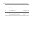
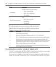

Label Description
AUX/MODEM
DualLED:Yellowontop,greenonbottom
• Yellow- DTR/DCD activity
• Green- TXD andRXD activity
• Off- Noactivity
[OneLEDforeachserialport]
Green
• Blinks-Ready,withactivity
• Solid- Ready
• Off- Notready
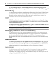
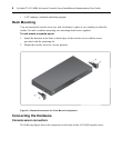
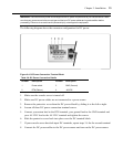
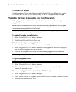
The following figure shows the rear connectors on the console server.
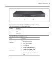
Figure 2.3: Rear of the Console Server (ACS 6032 Console Server Shown)
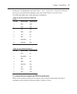
Number Description
1 Powersupplies(dualACshown).
2 Serialports(32portsshown).Modelscomewith4,8, 16,32or 48serialports.
3 ETH110/100M/1GEthernetport.Canbeconnectedtoasecondnetworkor usedfor failover.
4
AUX/Modemport.Ifanoptionalinternalmodemisordered,thisportisdefinedasaV.92
modem atthefactory;otherwise,theportisfactory-definedasRS-232withanRJ-45ACScon-
soleserver pinoutandcanbeusedtoconnecteither anexternalmodemor apower device.
5 ETH010/100M/1GEthernetportfor remoteIPaccess.
6
Consoleport.Allowsfor localadministrationandaccesstoconnecteddevicesthrougha ter-
minalor acomputer withaterminalemulator.
Table 2.3: Connectors on the Console Server Rear
Connecting device consoles or modems to serial ports
Use CAT 5 or greater cables and DB-9 or DB-25 console adaptors as needed to connect target
device consoles or modems to the serial ports on the console server.
The console server supports the Cisco
®
serial port pinout configuration, which is disabled by
default. If a Cisco cable is connected to a port, an administrator must enable the Cisco pinout
10 Cyclades™ ACS 6000 Advanced Console Server Installation/Administration/User Guide