


AXIS A1001 Network Door Controller & AXIS Entry Manager
Technical Specifications
Technical Specifications
AXIS A1001 Network Door Controller
Function/group
Item
Specications
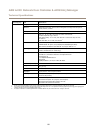
Models
AXIS A1001 Network Door Controller
Readers
Up to 2 readers per controller (Wiegand, RS485 (OSDP) with supported card formats
Doors 1–2 doors per controller
1
Credentials
Up to 15 000 with third-party access management software depending on server
capacity
Event history
30 000 First in First out (FIFO) per controller
Door controller
Access schedules Unlimited or third-party software dependent
I/O interface Reader I/0: DC output: 2x 12 V DC output max 300 mA; 2x 4 congurable
inputs/outputs, (digital input: 0 to max 40 V DC, digital output: 0 to max 40 V DC,
open drain, max 100 mA)
Reader data: RS485 full duplex, RS485 half duplex, Wiegand
Auxiliary: 1x 3.3 V DC output, max 100 mA, 2x congurable inputs/output (digital
input: 0 to max 40 V DC, digital output: 0 to max 40 V DC, open drain, max 100 mA)
Door connectors: 2x 2 input for door monitors and REX (digital input: 0 to
max 40 V DC)
Digital I/O
I/O functionality Precongured for readers and door monitors, Input trigger, Output toggle/pulse
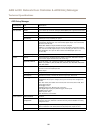
Security Password protection, IP address ltering, HTTPS
2
encryption, IEEE 802.1X network
access control, digest authentication, user access log
Network
Supported protocols IPv4, HTTP, HTTPS
2
, TLS
2
, QoS layer 3 DiffServ, FTP, SMTP, Bonjour, UPnP,
SNMPv1/v2c/v3(MIB-II), DNS, DynDNS, NTP, RTSP, RTP, TCP, UDP, IGMP, RTCP, ICMP,
DHCP, ARP, SOCKS
System
Integration
Application
Programming Interface
Open API for software integration, including VAPIX®; specications available at
www.axis.com
ONVIF Prole C, specications available at www.onvif.org
Support for access control as a service with One-Click Connection
Tamper detection
Removal of unit cover/tamper front
Removal of unit from wall/tamper back
Reader tamper
Event log
Congurable by time and topic, Alarm acknowledgement
Event actions
Notication via email, HTTP and TCP, External output port, Status LED
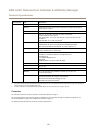
Events & Alarms
Event triggers Access Point: Access point enabled
Conguration: Access point changed, Access point removed, Area changed, Area
removed, Door changed, Door removed
Door: Door alarm, Door double-lock monitor, Door lock monitor, Door mode, Door
monitor, Door warning
Event Logger: Alarm
Hardware: Casing open, Network, peer connection
Input Signal Digital input port, Manual trigger, Virtual inputs
Schedule: Interval, Pulse
System: System ready
Time: Recurrence, Use schedule
54