


AXIS A1001 Network Door Controller & AXIS Entry Manager
Technical Specifications
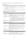
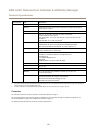
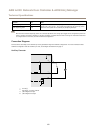
Network Connector
RJ45 Ethernet connector. Supports Power over Ethernet (PoE). Use Category 5e cables or higher.
Function
Specications
Power and Ethernet
Power over Ethernet IEEE 802.3af/802.3at Type 1 Class 3, 44–57 V DC
Max load on outputs = 7.5 W
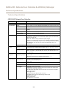
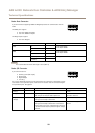
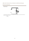
Power Lock Connector
4-pin terminal block for powering one or two locks (DC output). The lock connector can also
be used to power external devices.
Connect locks and loads to the pins according to the hardware pin chart generated through
the hardware conguration.
Function Pin Notes
Specications
0 V DC (-)
1, 3
0 V DC
0 V DC, oating, or
12 V DC
2, 4
For controlling up to two 12 V locks. Use the hardware
pin chart. See Congure the Hardware on page 13.
12 V DC
Max total load = 500 mA
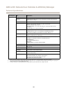
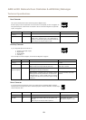
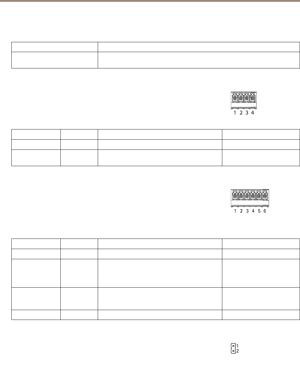
Power & Relay Connector
6-pin terminal block with built-in relay for:
• External devices
• Auxiliary power (DC output)
• 0 V DC (-)
Connect locks and loads to the pins according to the hardware pin chart generated through
the hardware conguration.
Function Pin Notes
Specications
0 V DC (-)
1, 4
0 V DC
Relay
2–3
For connecting relay devices. Use the hardware pin
chart. See Congure the Hardware on page 13.
The two relay pins are galvanically separated from the
rest of the circuitry.
Max current = 700 mA
Max voltage = +30 V DC
12 V DC
5
For powering auxiliary equipment.
Note: This pin can only be used as power out.
Max voltage = +12 V DC
Max load = 500 mA
24 V DC
6
Not used
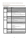
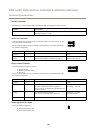
Tampering Alarm Pin Header
Two 2-pin headers for bypassing:
• Back tampering alarm (TB)
• Front tampering alarm (TF)
60