


AXIS A1001 Network Door Controller & AXIS Entry Manager
Technical Specifications
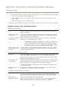
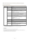
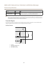
Reader Data Connector
6-pin terminal block supporting RS485 and Wiegand protocols for communication with the
reader.
The RS485 ports support:
• Two-wire RS485 half duplex
• Four-wire RS485 full duplex
The Wiegand ports support:
• Two-wire Wiegand
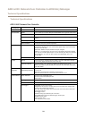
Function Pin Notes
A-
1
RS485
B+
2
For full duplex RS485
For half duplex RS485
A-
3
RS485
B+
4
For full duplex RS485
For half duplex RS485
D0 (Data 0)
5
Wiegand
D1 (Data 1)
6
For Wiegand
Important
The recommended maximum cable length is 30 m (98.4 ft).
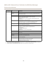
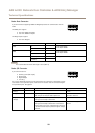
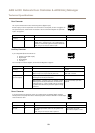
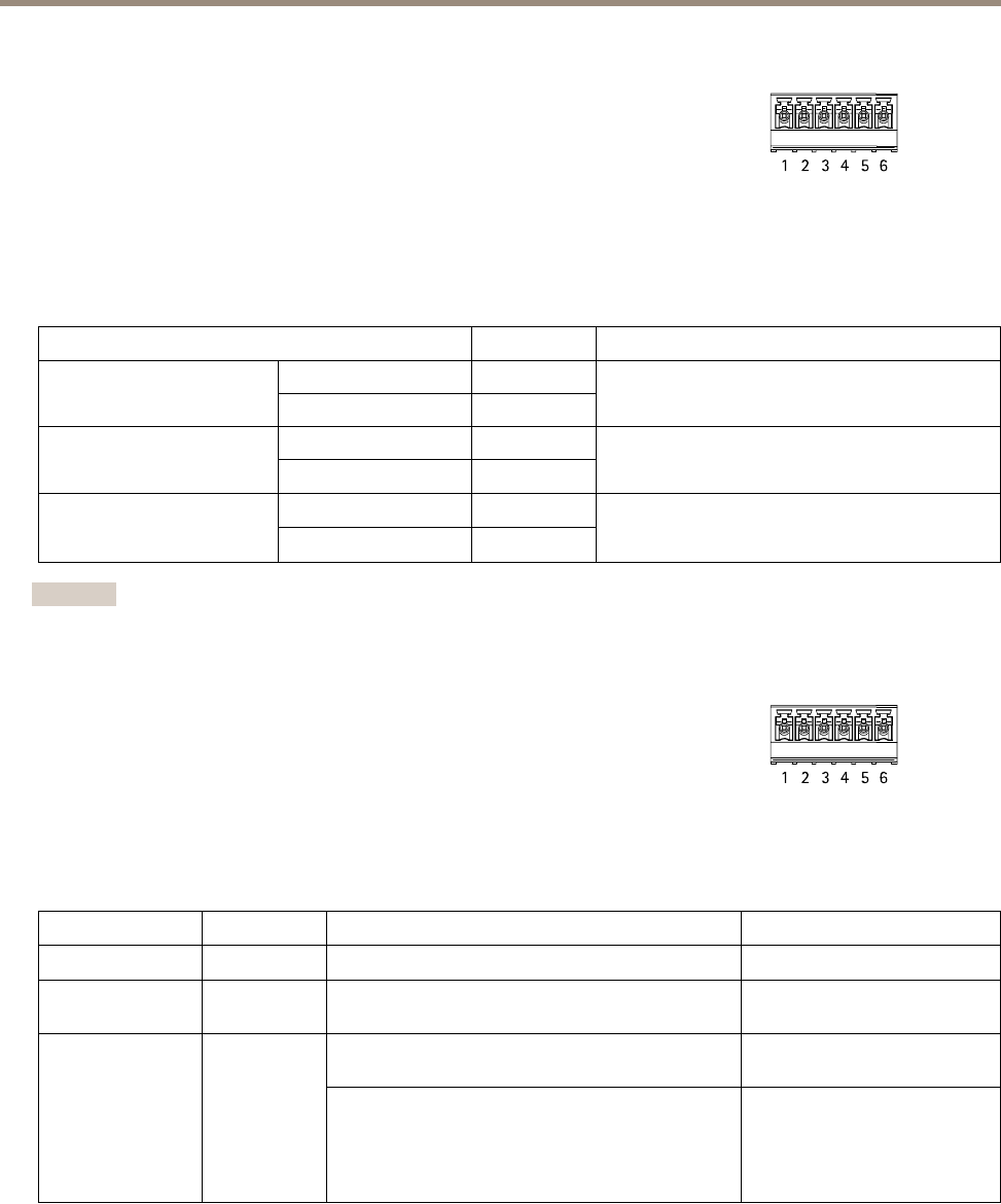
Reader I/O Connector
6-pin terminal block for:
• Auxiliary power (DC output)
• Digital Input
• Digital Output
• 0 V DC (-)
Pin 3 on the reader I/O connectors can be supervised. If the connection is interrupted, an event
is activated. To use supervised inputs, install end of line resistors. Use the connection diagram
for supervised inputs. See page 62.
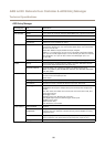
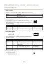
Function Pin Notes
Specications
0 V DC (-)
1
0 V DC
DC output
2
For powering auxiliary equipment.
Note: This pin can only be used as power out.
12 V DC
Max load = 300 mA
Digital input — Connect to pin 1 to activate, or leave
oating (unconnected) to deactivate.
0 to max 40 V DC
Congurable (Input
or Output)
3–6
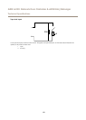
Digital output — Connect to pin 1 to activate, or leave
oating (unconnected) to deactivate. If used with an
inductive load, e.g. a relay, a diode must be connected
in parallel with the load, for protection against voltage
transients.
0 to max 40 V DC, open drain,
100 mA
58