


AXIS A1001 Network Door Controller & AXIS Entry Manager
Technical Specifications
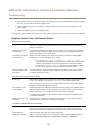
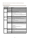
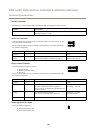
Door Connector
Two 4-pin terminal blocks for door monitoring devices (digital input).
All door input pins can be supervised. If the connection is interrupted, an alarm is triggered. To
use supervised inputs, install end of line resistors. Use the connection diagram for supervised
inputs. See page 62.
Function Pin Notes
Specications
0 V DC (-)
1, 3
0 V DC
Input
2, 4
For communicating with door monitor.
Digital input — Connect to pin 1 or 3 respectively to
activate, or leave oating (unconnected) to deactivate.
Note: This pin can only be used for input.
0 to max 40 V DC
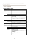
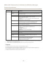
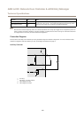
Auxiliary Connector
4-pin congurable I/O terminal block for:
• Auxiliary power (DC output)
• Digital Input
• Digital Output
• 0 V DC (-)
For an example connection diagram, see Connection Diagrams on page 61.
Function Pin Notes
Specications
0 V DC (-)
1
0 V DC
DC output
2
For powering auxiliary equipment.
Note: This pin can only be used as power out.
3.3 V DC
Max load = 100 mA
Digital input — Connect to pin 1 to activate, or leave
oating (unconnected) to deactivate.
0 to max 40 V DCCongurable
(Input or Output)
3–4
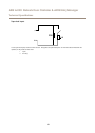
Digital output — Connect to pin 1 to activate, or leave
oating (unconnected) to deactivate. If used with an
inductive load, e.g. a relay, a diode must be connected
in parallel with the load, for protection against voltage
transients.
0 to max 40 V DC, open drain,
100 mA
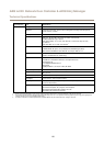
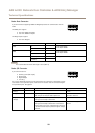
Power Connector
2-pin terminal block for DC power input. Use a Safety Extra Low Voltage (SELV) compliant
limited power source (LPS) with either a rated output power limited to ≤100 W or a rated output
current limited to ≤5 A.
Function Pin Notes
Specications
0 V DC (-)
1
0 V DC
DC input
2
For powering controller when not using Power over
Ethernet.
Note: This pin can only be used as power in.
10–30 V DC, max 26 W
Max load on outputs = 14 W
59