


AXIS A1001 Network Door Controller & AXIS Entry Manager
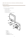
Hardware Overview
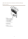
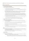
Power Outputs
Power Lock Connector
4-pin terminal block for connecting one or two locks. The lock connector can also be used to power external devices. For
specications, see page 60.
Power & Relay Connector
6-pin terminal block for connecting power and the door controller’s relay to external devices such as locks and sensors. For
specications, see page 60.
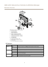
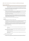
Buttons and Other Hardware
Tampering Alarm Pin Header
Two 2-pin headers for disconnecting the front and back tampering alarms. For specications, see page 60.
Control Button
The control button is used for:
• Resetting the product to factory default settings. See page 50.
• Connecting to an AXIS Video Hosting System service. See page 45. To connect, press and hold the button for about 1
second until the Status LED ashes green.
• Connecting to AXIS Internet Dynamic DNS Service. See page 45. To connect, press and hold the button for about 3 seconds.
9