


AXIS A1001 Network Door Controller & AXIS Entry Manager
Technical Specifications
Function/group
Item
Specications
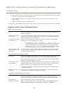
Casing
Plastic
Software Conguration and basic access control management through Internet Explorer,
Firefox, Chrome, or Safari
Memory
256 MB RAM, 4 Gbit Flash
Power
Power in: 10–30 V DC, max 26 W or Power over Ethernet
IEEE 802.3af/802.3at Type 1 Class 3
Power out & relay: 1x 12 V DC, max 500 mA 1x solid state relay 30 V DC,
max 700 mA
Power out lock: 2x 12 V DC, max 500 mA
1
Connectors
RJ45 10BASE-T/100BASE-TX
Terminal blocks: DC power, 10 Inputs/Outputs, RS485/Wiegand, Relay
Cable size for connectors: CSA: AWG 28–16, CUL/UL: AWG 30–14
Operating conditions
0 °C to 50 °C (32 °F to 122 °F)
Humidity 20–85% RH (non-condensing)
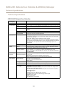
Approvals
EN 55022 Class B, EN 50130-4, EN 61000-3-2, EN 61000-3-3, EN 55024,
EN 61000-6-1, EN 61000-6-2FCC Part 15 Subpart B Class B
ICES-003 Class B
C-tick AS/NZS CISPR22 Class B
VCCI Class B
IEC/EN/UL 60950-1, UL 294, UL 2043, EN 50581
Dimensions (HxWxD)
45.5 x 180 x 180 mm (1.8 x 7.1 x 7.1 in)
Weight
500 g (1.1 lb)
Included accessories
Connector kit, Cable ties, Installation Guide
Warranty Axis 3-year warranty with possibility to extend up to 5 years, see
www.axis.com/warranty
General
Optional accessories AXIS T8120 Midspan 15 W
AXIS T8128 PoE Splitter 24 V (requires 30 W midspan)
AXIS T8129 PoE Extender Mains adaptor 24 V DC
AXIS T98A15-VE Surveillance Cabinet
3
1. Power consumption dependent; max load for readers and other equipment is 7.5 W with PoE and 14 W with 10–30 V DC.
2. This product includes software developed by the OpenSSL Project for use in the OpenSSL Toolkit (http://www.openssl.org/), and cryptographic
software written by Eric Young (eay@cryptsoft.com)
3. In outdoor installations combining AXIS A1001 and AXIS T98A15-VE, the allowed maximum voltage is 30 V DC.
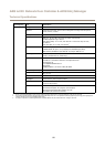
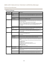
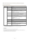
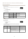
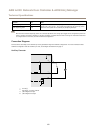
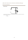
Connectors
For information about the connectors’ positions, see Hardware Overview on page 5 .
For connection diagrams and information about the hardware pin chart generated through the hardware conguration, see
Connection Diagrams on page 61 and Congure the Hardware on page 13.
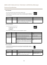
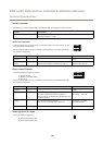
The following section describes the connectors’ technical specications.
57