


AXIS A1001 Network Door Controller & AXIS Entry Manager
Technical Specifications
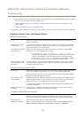
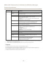
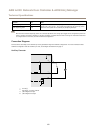
Function Pin Notes
Back tampering alarm
1–2
Front tampering alarm
1–2
To bypass the front and back tampering alarm simultaneously, connect jumpers
between TB 1, TB 2 and TF 1, TF 2 respectively. Bypassing the tampering alarms
means that the system will not identify any tampering attempts.
Note
Both the front and back tampering alarms are connected by default. The casing open trigger can be congured to perform an
action if the door controller is opened or if the door controller is removed from the wall or ceiling. For information about how
to congure alarms and events, see Alarm and Event Conguration.
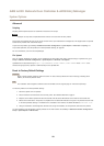
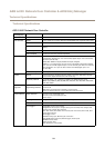
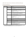
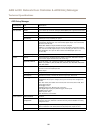
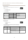
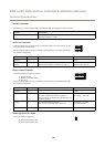
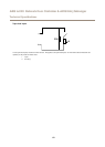
Connection Diagrams
Connect devices according to the hardware pin chart generated through the hardware conguration. For more information about
hardware conguration and the hardware pin chart, see Congure the Hardware on page 13.
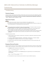
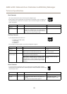
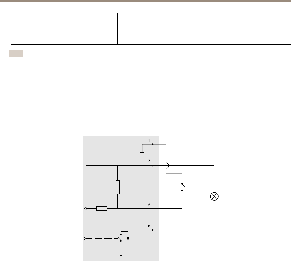
Auxiliary Connector
1
2
A
B
1
0 V DC (-)
2
DC output: 3.3 V, max 100 mA
A
I/O congured as input
B
I/O congured as output
61