


AXIS A1001 Network Door Controller & AXIS Entry Manager
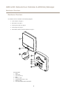
Hardware Overview
Green Steady when not energized.
Red
Steady when energized.
Lock
Unlit Floating.
Note
• The Status LED can be congured to ash while an event is active.
• The Status LED can be congured to ash for identifying the unit. Go to Setup > Additional Controller Conguration >
System Options > Maintenance .
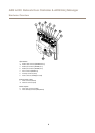
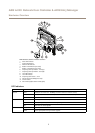
Connectors and Buttons
For technical specications, see page 54.
I/O Interface
Reader Data Connector
Two 6-pin terminal blocks supporting RS485 and Wiegand protocols for communication with the reader. For specications, see
page 58.
Reader I/O Connector
Two 6-pin terminal blocks for reader input and output. In addition to the 0 V DC reference point and power (DC output), the
reader I/O connector provides the interface to:
• Digital input – For connecting, for example, reader tampering alarms.
• Digital output – For connecting, for example, reader beepers and reader LEDs.
For specications, see page 58.
Door Connector
Two 4-pin terminal blocks for connecting door monitoring devices and request to exit (REX) devices. For specications, see page 59.
Auxiliary Connector
4-pin congurable I/O terminal block. Use with external devices, in combination with, for example tampering alarms, event triggering
and alarm notications. In addition to the 0 V DC reference point and power (DC output), the auxiliary connector provides the
interface to:
• Digital input – An alarm input for connecting devices that can toggle between an open and closed circuit, for example PIR
sensors or glass break detectors.
• Digital output – For connecting external devices such as burglar alarms, sirens or lights. Connected devices can be
activated by the VAPIX® application programming interface or by an action rule.
For specications, see page 59.
External Power Inputs
NONO
NO
TICETICE
TICE
The product shall be connected using a shielded network cable (STP). All cables connecting the product to the network shall
be intended for their specic use. Make sure that the network devices are installed in accordance with the manufacturer’s
instructions. For information about regulatory requirements, see Electromagnetic Compatibility (EMC) on page 2 .
Power Connector
2-pin terminal block for DC power input. Use a Safety Extra Low Voltage (SELV) compliant limited power source (LPS) with either a
rated output power limited to ≤100 W or a rated output current limited to ≤5 A. For specications, see page 59.
Network Connector
RJ45 Ethernet connector. Supports Power over Ethernet (PoE). For specications, see page 60.
8