


Confidential
2-12
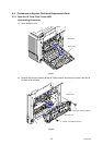
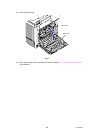
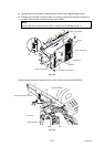
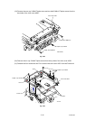
(8) Remove the two cup B M4x12 Taptite screws and two cup S M4x8 Taptite screws.
(9) Release the one Hook on the front side, two Hooks on the bottom and the two Hooks on
the back side, and then remove the Side cover R ASSY.
Note:
When removing the Side cover R ASSY, be careful not to damage section “A”.
Fig. 2-14
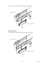
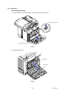
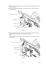
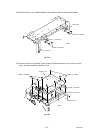
(10) Disconnect the three Connectors (CN1, CN2, CN4) from the Driver PCB ASSY.
Fig. 2-15
Taptite, cup S M4x8
Hooks
Side cover R ASSY
“A”
Taptite, cup S M4x8
Taptite, cup B M4x12
Hooks
<Right side>
9a
9b
Hook
Driver PCB ASSY
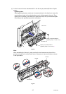
<Left side>
CN2
CN1
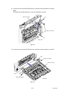
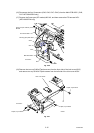
Document scanner unit ASSY
CN4
Main PCB ASSY