


Confidential
2-24
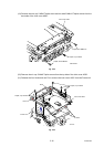
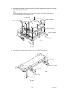
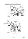
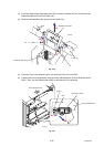
(14) Assemble the FG harness FB with the one cup S M3x6 Taptite screw.
(15) Assemble the FG harness ADF with the one cup S M3x6 Taptite screw.
Fig. 2-38
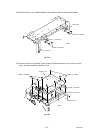
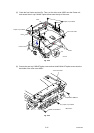
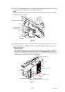
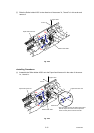
(16) Connect the three Connectors (CN1, CN2, CN4) into the Driver PCB ASSY.
Fig. 2-39
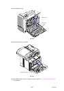
Document scanner unit ASSY
Driver PCB shield
FG harness ADF
FG harness FB
Taptite, cup S M3x6
Taptite, cup S M3x6
Driver PCB ASSY
<Left side>
CN4
CN2
CN1
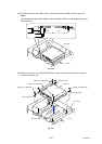
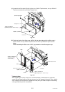
Document scanner unit ASSY
Main PCB ASSY
<Left side>