


Confidential
3-163
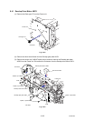
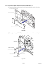
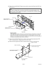
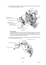
(6) Remove the six bind B M4x12 Taptite screws, and then remove the Drum drive ASSY from
the Frame unit.
Note:
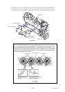
Since the four Gears 39/121 of the Drum drive ASSY are assembled together, which
makes one set, DO NOT replace only one gear. If their replacement is required, replace
the complete Drum drive ASSY.
Fig. 3-239
*1
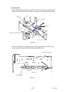
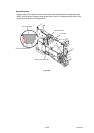
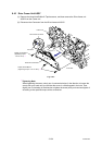
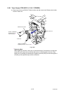
Tightening Note:
When tightening the screw, slowly turn it counterclockwise (in the direction to loosen the
screw) with your hand until you feel that the screw is a little dropped in the hole. Then,
slightly turn it clockwise (in the direction to tighten the screw) with your hand and tighten it
according to the specified torque with a screwdriver.
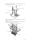
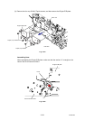
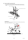
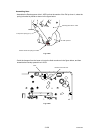
(7) Remove the bind S M3x6 Taptite screw, and then remove the Drum phase sensor PCB
ASSY 2 (whose harness is longer) from the Drum drive ASSY.
(8) Remove the Drum phase sensor PCB 1 (whose harness is shorter) in the same way.
Fig. 3-240
Taptite, bind S M3x6
Drum phase sensor PCB ASSY 2
(whose harness is longer)
Taptite, bind S M3x6
Drum phase sensor PCB ASSY 1
(whose harness is shorter)
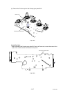
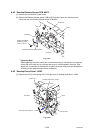
Positioning pin
Drum drive ASSY
Drum drive ASSY
Taptite, bind B M4x12
(Tightening torque: 1.20 ±0.1 N m) *1
Frame unit
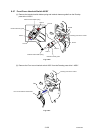
Taptite, bind B M4x12
(Tightening torque: 1.20 ±0.1 N m) *1 <Left side>
Gears 39/121
Gears 39/121