


Confidential
3-184
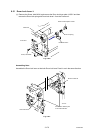
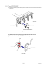
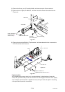
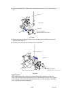
(3) Remove the Screw pan (S/P washer) M4x8, and then remove the Ground terminal.
(4) Remove the two Taptite, flat B M3x10, and then remove the Power inlet socket from the
Frame unit.
Fig. 3-275
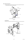
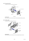
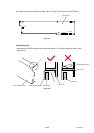
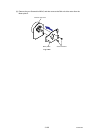
(5) Remove the three bind B M4x12 Taptite screws, and then release the Hook to remove the
PS PCB unit from the Frame unit.
Fig. 3-276
*1
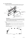
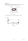
Tightening Note:
When tightening the screw, slowly turn it counterclockwise (in the direction to loosen the
screw) with your hand until you feel that the screw is a little dropped in the hole. Then, slightly
turn it clockwise (in the direction to tighten the screw) with your hand and tighten it according
to the specified torque with a screwdriver.
Frame unit
Ground terminal
Power inlet socket
Taptite, flat B M3x10
(Tightening torque:
0.60 ±0.1 N m) *1
Screw pan
(S/P washer) M4x8
<Back side>
PS PCB unit
Taptite, bind B M4x12
(Tightening torque: 0.90 ±0.1 N m) *1
Frame unit
Hook
<Right side>