


Confidential
3-59
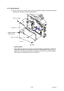
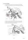
8.17 Driver PCB ASSY
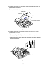
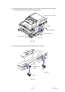
(1) Disconnect the three Connectors (CN1, CN2, CN4) from the Driver PCB ASSY.
(2) Release the Lock and disconnect the Connector (CN3) from the Driver PCB ASSY.
Fig. 3-49
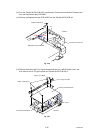
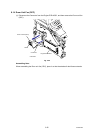
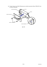
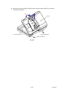
(3) Remove the cup S M3x6 Taptite screw, and then remove the FG harness ADF.
(4) Remove the cup S M3x6 Taptite screw, and then remove the FG harness FB.
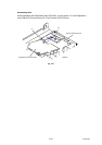
(5) Remove the Driver PCB ASSY and Driver PCB shield.
Fig. 3-50
Driver PCB ASSY
CN4
CN1
CN2
CN3
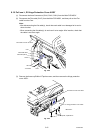
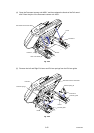
Document scanner unit ASSY
Taptite, cup S M3x6
FG harness FB
Document scanner unit ASSY
Driver PCB shield
Driver PCB ASSY
FG harness ADF
Taptite, cup S M3x6
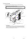
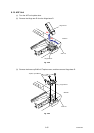
<Left side>
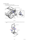
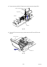
<Left side>
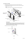
Main PCB ASSY
Lock