


Confidential
3-162
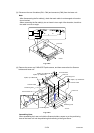
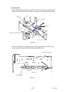
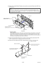
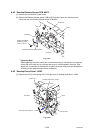
(4) Remove the two cup S M3x6 Taptite screws, and then remove the Drum drive motor 1.
(5) Remove the two cup S M3x6 Taptite screws, and then remove the Drum drive motor 2.
Fig. 3-237
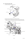
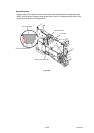
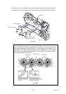
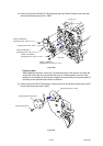
Assembling Note:
The two Gears 39/121 which are engaged with the same motor are phased with each
other when assembling the Drum drive ASSY. If removing the motor to replace it, the
gears may be out of phase. When replacing the motor, therefore, be sure to phase the
Gears 39/121, and then assemble the motor. For the method how to phase the gears,
refer to the figure below (Fig. 3-238).
Fig. 3-238
Frame unit
Taptite, cup S M3x6
Drum drive motor 2
Taptite, cup S M3x6
Drum drive motor 1
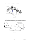
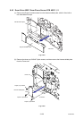
<Left side>
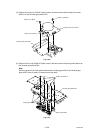
Gears 39/121
Gears 39/121
Drum drive ASSY
A
lign the mark on the Gear
with the line on the Drum
drive plate.
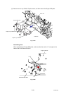
A
lign the mark on the Gear with
the space between the two lines
on the Drum drive plate.