


Confidential
3-178
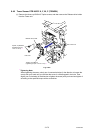
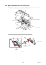
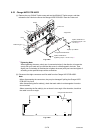
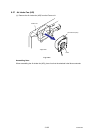
8.53 Charge HVPS PCB ASSY
(1) Remove the cup S M3x6 Taptite screw and two bind B M4x12 Taptite screws, and then
release the four Hooks to remove the Charge HVPS PCB ASSY from the Frame unit.
Fig. 3-264
*1
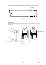
Tightening Note:
When tightening the screw, slowly turn it counterclockwise (in the direction to loosen the
screw) with your hand until you feel that the screw is a little dropped in the hole. Then,
slightly turn it clockwise (in the direction to tighten the screw) with your hand and tighten it
according to the specified torque with a screwdriver.
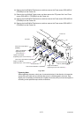
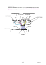
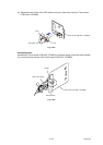
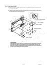
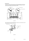
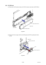
(2) Disconnect the eight connectors and flat cable from the Charge HVPS PCB ASSY.
Note:
- When disconnecting the connectors, they may be damaged if pulling the Charge HVPS
PCB ASSY by force.
- After disconnecting the flat cable(s), check that each cable is not damaged at its end or
short-circuited.
- When connecting the flat cable(s), do not insert it at an angle. After insertion, check that
the cable is not at an angle.
CN1
CN3
CN9
CN5
CN6 CN7
CN2
CN8
CN4
Fig. 3-265
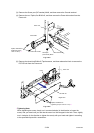
Charge HVPS PCB ASSY
Hooks
Charge HVPS PCB ASSY
Taptite, bind B M4x12
(Tightening torque: 1.20
±0.1 N m) *1
Taptite, cup S M3x6
Taptite, bind B M4x12
(Tightening torque: 1.20 ±0.1 N m) *1
Positioning pin
Hook
Frame unit
<Right side>