


Confidential
3-47
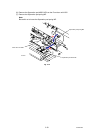
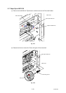
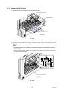
8.10 Transfer HVPS PCB Unit
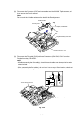
(1) Disconnect the four Connectors from the Electrode head.
Fig. 3-29
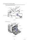
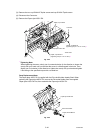
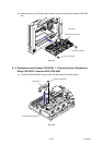
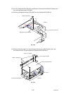
(2) Disconnect the flat cable (CN1) and two connectors (CN5, CN8) from the Registration relay
PCB unit.
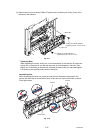
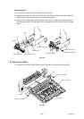
Note:
- After disconnecting the flat cable(s), check that each cable is not damaged at its end or
short-circuited.
- When connecting the flat cable(s), do not insert it at an angle. After insertion, check that
the cable is not at an angle.
CN8
CN5
CN1
Fig. 3-30
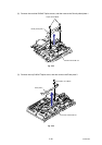
Connector
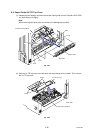
Transfer HVPS PCB unit
Electrode head
Registration relay PCB ASSY
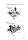
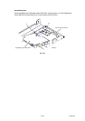
Transfer HVPS PCB unit
<Back side>
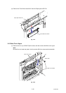
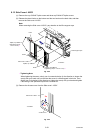
<Back side>