


Confidential
2-13
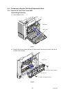
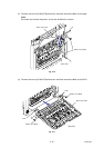
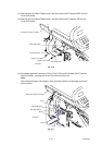
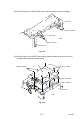
(11) Remove the cup S M3x6 Taptite screw, and then remove the FG harness ADF from the
Driver PCB shield.
(12) Remove the cup S M3x6 Taptite screw, and then remove the FG harness FB from the
Driver PCB shield.
Fig. 2-16
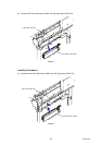
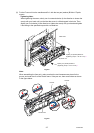
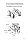
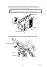
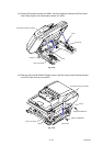
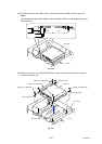
(13) Disconnect the three Connectors (CN14, CN16, CN21) and Flat cable (CN17) from the
Main PCB ASSY, and then pull out the Flat cable from the Core.
Note:
After disconnecting the Flat cable(s), check that each cable is not damaged at its end or
short-circuited.
Fig. 2-17
FG harness ADF
Main PCB ASSY
Taptite, cup S M3x6
Taptite, cup S M3x6
FG harness FB
CN14
CN21
Flat cable (CN17)
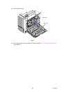
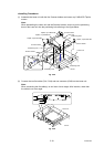
<Left side>
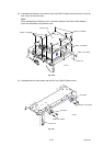
<Left side>
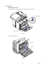
Document scanner unit ASSY
Driver PCB shield
Document scanner unit ASSY
CN16
Core