


Index
IN-4
Cisco CRS-1 Carrier Routing System 16-Slot Multishelf System Site Planning Guide
OL-7422-04
DC power load zones, SFC side 3-29
fabric cable turn collar 3-18
fabric card chassis (front) 1-6
fabric card chassis (rear) 1-7
four-FCC multishelf system 1-3, 1-4
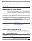
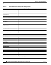
multishelf system floor plan 3-5
NEBS bonding and grounding points 2-11
single-FCC multishelf system 1-2
switch fabric plane, single-module 3-10
two-FCC multishelf system 1-3
floor plan 2-16, 2-17
chassis access 4-5
multishelf system 3-5
footprint, fabric card chassis 2-16
G
ground cable lug 2-11
grounding
points, NEBS
2-10, 2-11
requirements 2-3
H
handling
cable slack
3-14
fabric cables 3-16, 4-6
fiber-optic cables 3-16
handling optical array cables 2-23
heat dissipation, fabric card chassis 2-14, B-3
high availability
cable runs
3-15
planning for 3-21, 3-22
S2 fabric card placement (table) 3-24, 3-25, 3-26
hole pattern 2-15
humidity guidelines, system B-3
I
installation
bolting the chassis to the floor
2-15
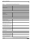
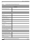
checklist (table) C-1
kit 2-15
See also site planning
installation checklist
C-5
See also site planning
installation site requirements
4-4
interface cables, considerations for installing 3-14
L
labeling fabric cables 3-17
line card chassis, components 1-8
M
maintenance access, chassis 4-5
midplane, line card chassis 1-8
moving the chassis
considerations
3-6
transport dolly 4-3
moving the fabric card chassis 2-19
multishelf system
aisle clearances
3-6
cabling 3-13, 3-14, 3-16, 3-17
Cat 6509 Switch 1-9
components 1-1, 3-2
configuration requirements 3-2, 3-3
control network
illustration
3-11, 3-12
introduction 1-9
requirements 3-3, 3-4
designated shelf controller (DSC) 3-16
fabric cables 3-17
fabric card chassis 1-5
floor plan 3-5