


2-10
Cisco CRS-1 Carrier Routing System 16-Slot Multishelf System Site Planning Guide
OL-7422-04
Chapter 2 16-Slot Fabric Card Chassis Installation Site Requirements
Fabric Card Chassis Power System Requirements
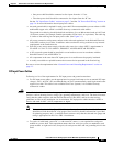
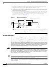
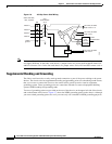
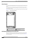
Figure 2-6 AC Wye Power Shelf Wiring
Note The same AC rectifiers are used in both the fabric and line card chassis; however, the AC power shelves
are slightly different. In the fabric card chassis, a jumper on the AC power shelf backplane limits PS1
and PS2 current to 26 A. In the line card chassis, no jumper exists, and so PS1 and PS2 current is 40 A.
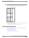
Supplemental Bonding and Grounding
The fabric card chassis has a safety earth ground connection as part of the power cabling to the power
shelves. The chassis also has supplemental bonding and grounding points (two threaded ground inserts)
that you can use to connect the chassis to the central office ground system or interior equipment
grounding system. These grounding points are sometimes referred to as network equipment building
system (NEBS) bonding and grounding studs.
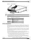
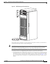
Two sets of grounding points are provided on the rear of the chassis: on the upper left side of the chassis
and on the bottom of the chassis. Figure 2-7 shows the NEBS grounding points on the chassis. Although
you can use both grounding points in a set if you want, only one is needed for NEBS grounding purposes.
138088
TBI
CB1
shelf ON/OFF
30 A
Phase A
Phase B
Phase C
Safety
ground
Alarm
and
service
processor
assemblies
54.5 VDC, 40 ADC
load zones 1 & 3
54.5 VDC, 26 ADC
load zone 2
System
communication
PS
status
signals
PS
status
signals
PS2
4.4 kW
54.5 VDC, 26 ADC
load zone 4
Neutral
PS0
4.4
kW
PS1
4.4
kW
200-to-240 VAC,
30 A, 3-phase