


1-5
Cisco CRS-1 Carrier Routing System 16-Slot Multishelf System Site Planning Guide
OL-7422-04
Chapter 1 Cisco CRS-1 16-Slot Multishelf System Overview
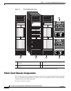
Fabric Card Chassis Components
• Eight S2 switch fabric cards. These cards provide Stage 2 of the three-stage Benes switch fabric for
the multishelf system. S13 switch fabric cards in the line card chassis provide Stage 1 and Stage 3
of the switch fabric. When multiple FCCs are installed in a multishelf system, the S2 switch fabric
cards are distributed across the FCCs.
The switch fabric receives user data from one MSC and PLIM pair and performs the switching
necessary to route the data to the appropriate egress MSC and PLIM pair.
• Optical interface modules (OIMs) and cables. Each S2 fabric card plugs into one side of an OIM,
and the multishelf system fabric cables plug into the other side of the OIM. The fabric cables are
optical array cables that are installed between the FCCs and LCCs to connect the S2 and S13 fabric
cards to each other.
• Two 2-port shelf controller Gigabit Ethernet (SCGE) cards. These cards control the S2 switch fabric
cards. They also control the chassis fans, varying their speed to adjust the airflow for ambient
conditions. Only one shelf controller card is active at a time. The second acts as a “standby” shelf
controller, serving as a backup if the active card fails.
or
• Two 22-port shelf controller Gigabit Ethernet (SCGE) cards. These cards control the S2 switch
fabric cards. They also control the chassis fans, varying their speed to adjust the airflow for ambient
conditions. Only one shelf controller card is active at a time. The second acts as a “standby” shelf
controller, serving as a backup if the active card fails. The 22-port SCGE card also includes
integrated switching functionality. This eliminates the need for the 2-port SCGE cards and external
Cisco Catalyst switches.
• A power system that provides 8800 watts (8.8 kW) of redundant DC output power for the chassis.
The AC power system consists of two AC power shelves with three AC rectifier modules in each
power shelf. The DC power system consists of two DC power shelves with two DC power entry
modules (PEMs) in each power shelf. Each power shelf supplies input power to the rectifiers
or PEMs, which in turn provide processed power to the chassis.
• Two alarm modules. The alarm modules provide external alarm system connections. The alarm
modules are located in the AC or DC power shelves.
• A chassis backplane. The backplane distributes power to the components in the chassis and connects
the components to each other. The S2 switch fabric cards and shelf controller cards plug into the
backplane. The backplane is not field replaceable by the customer.
• Upper and lower fan trays. The fan trays contain fans that push and pull air through the chassis.
A removable air filter is also located above the lower fan tray.
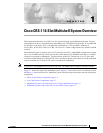
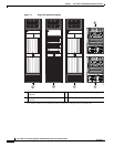
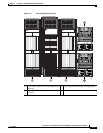
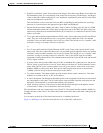
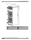
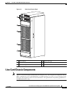
The switch fabric cards are located at the front of the FCC. The optical interface modules (OIMs) are
located at the rear of the chassis. The fabric cables (that interconnect the switch fabric cards) plug into
the OIMs.
Cool air enters at the front of the chassis and warm air is exhausted at the rear.
Figure 1-4 and Figure 1-5 show the front and rear views of the fabric card chassis.