


1-8
Cisco CRS-1 Carrier Routing System 16-Slot Multishelf System Site Planning Guide
OL-7422-04
Chapter 1 Cisco CRS-1 16-Slot Multishelf System Overview
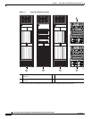
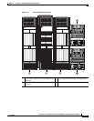
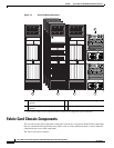
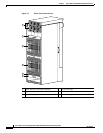
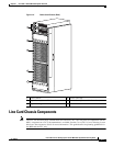
Line Card Chassis Components
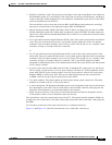
The Cisco CRS-1 LCC contains:
• As many as 16 modular services cards (MSCs), also called line cards, and 16 physical layer interface
modules (PLIMs) or SPA interface processors (SIPs). The MSC and PLIM or SIP are an associated
pair of cards that mate through the chassis midplane. The MSC provides the forwarding engine for
Layer 3 routing of user data, and the PLIM or SIP provides the physical interface and connectors for
the user data.
PLIMs and SIPs are described in the following documents:
–
Cisco CRS-1 Carrier Routing System Packet-over-SONET/SDH Physical Layer Interface
Module (PLIM) Installation Note
–
Cisco CRS-1 Carrier Routing System Gigabit Ethernet Physical Layer Interface Module
(PLIM) Installation Note
–
Cisco CRS-1 SIP and SPA Hardware Installation Guide
• A chassis midplane. The midplane connects MSCs to their associated PLIMs and allows an MSC to
be removed from the chassis without having to disconnect the cables that are attached to the
associated PLIM. The midplane distributes power, connects the MSCs to the switch fabric cards,
and provides control plane interconnections. The midplane is not field replaceable by the customer.
• Two route processor cards (RPs). The RPs provide the intelligence of the system by functioning as
the LCC system controller and performing route processing. Only one RP is active at a time. The
second RP acts as a “standby” RP, serving as a backup if the active RP fails.
The RP also monitors system alarms and controls the system fans. LEDs on the front panel indicate
active alarm conditions.
• (Optional) One or more distributed route processor cards (DRPs), each with a corresponding PLIM.
Each DRP and DRP PLIM function as an additional route processor (RP) in the system, providing
additional route processing for the Cisco CRS-1 router. By offloading processor-intensive tasks
(such as BGP speakers and ISIS) from the RP to the DRP, you can improve system performance.
• Eight switch fabric cards. These fabric cards provide switch fabric components for the system. The
switch fabric receives user data from one MSC and PLIM pair and performs the switching necessary
to route the data to the appropriate egress MSC and PLIM pair.
–
As a standalone system (single shelf), the LCC contains S123 fabric cards that provide all three
stages of the three-stage Benes switch fabric.
–
As part of a multishelf system, the LCC contains S13 fabric cards that provide Stage 1 and Stage
3 of the switch fabric. S2 fabric cards in the FCCs provide Stage 2 of the fabric, and fabric cables
connect the fabric cards to each other.
• Two fan controller cards. These cards control the chassis fans, varying their speed to adjust the
airflow for ambient conditions.
• Two AC or two DC power shelves with three AC rectifiers or DC power entry modules (PEMs) in
each power shelf. The power shelves and AC rectifiers or DC PEMs provide 13.2 kilowatts of
redundant power for the system.
• Two alarm modules. The alarm modules provide external alarm system connections. The alarm
modules are located in the AC or DC power shelves.
• Upper and lower fan trays. The fan trays contain fans that push and pull air through the chassis.
A removable air filter is located above the lower fan tray.