


3-6
Cisco CRS-1 Carrier Routing System 16-Slot Multishelf System Site Planning Guide
OL-7422-04
Chapter 3 Multishelf System Planning
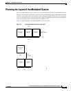
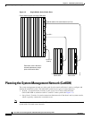
Planning the Layout of the Multishelf System
Note The aisles between equipment rows should be wide enough to allow the LCCs or FCCs to be pulled out
into the aisle, turned around, and maneuvered into position. The amount of clearance required to turn
the chassis in the aisle is approximately:
50 in. (127 cm)—Chassis without cosmetics and doors (and without the transport dolly)
60 in. (152.4 cm)—Chassis with the transport dolly attached
General Site Planning Considerations
As you plan the installation site for your multishelf system, be sure to plan for the considerations
described in the following sections.
Considerations for Moving the Chassis
• Are the aisles between equipment rows wide enough to use the Cisco dolly to move the chassis into
position? If not, how do you plan to move the chassis? The dolly requires the following aisle
clearances (not including the space for mover’s hands):
• 50 in. (127 cm)—To move the chassis on the dolly in its 180-degree configuration. This
configuration is preferred for moving the chassis.
• 24 inches (61 cm)—To move the chassis on the dolly in its 90-degree configuration. To avoid
tipping the chassis, use extra care when moving the chassis in this configuration.
• Before you move the Cisco CRS-1 chassis using the Cisco dolly, be sure to:
–
Remove the power shelves and cards from the chassis. You can leave the fan trays installed.
Do not attempt to move the chassis with components installed. It is too heavy.
–
Install impedance carriers in the card slots. Do not move the chassis without the carriers installed.
–
Note that carpet tiles are useful for sliding the chassis along the floor.
Considerations for System Access
• Will existing equipment need to be moved to accommodate the multishelf system chassis?
• Do you have to move equipment that is bolted to the floor? If so, be sure to remove the bolts and
save them for reinstallation.
If you are moving equipment to a new location, be sure to drill new bolt holes for the equipment in
the floor at the new location. If you are moving an existing Cisco CRS-1 chassis, note that an
aluminum plate template (CRS-LCC-DRILLTEMP) is available that shows the chassis footprint and
the pattern of holes that must be drilled into the floor for the chassis mounting brackets.
• Be sure to leave enough space at the front and rear of each chassis for maintenance access (for
example, to install and remove components, access cables, and so on).
• Make sure that you can access the MSC and S13 (rear) side of the LCC and the optical interface
module (OIM) side of the FCC, which is where the fabric cables are installed.