


3-29
Cisco CRS-1 Carrier Routing System 16-Slot Multishelf System Site Planning Guide
OL-7422-04
Chapter 3 Multishelf System Planning
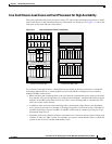
Power Redundancy and Card Placement for High Availability
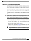
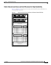
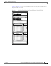
Figure 3-9 and Figure 3-10 show the power load zones on the front (SFC) and rear (OIM) sides of a
DC-powered fabric card chassis.
Figure 3-9 Fabric Card Chassis Power Load Zones, DC-Powered Chassis (SFC Side)
138057
A0
B0
A1
Power Shelf (PS0)
Power Shelf (PS1)
Fan Tray (FT0)
S
F
C
0
S
F
C
1
S
F
C
2
S
F
C
3
S
F
C
4
S
F
C
5
S
F
C
6
S
F
C
7
S
F
C
8
S
F
C
9
S
F
C
10
S
F
C
11
S
C
G
E
0
S
F
C
12
S
F
C
13
S
F
C
14
S
F
C
15
S
F
C
16
S
F
C
17
S
F
C
18
S
F
C
19
S
F
C
20
S
F
C
21
S
F
C
22
S
F
C
23
S
C
G
E
1
Upper SFC Card Cage
Lower SFC Card Cage
Fan Tray (FT1)
B1
AM0
AM1
Zone 3 Zone 4
Zone 1 Zone 2
Z1 Z2 Z3 Z4
Z1 Z2 Z3 Z4