


3-9
Cisco CRS-1 Carrier Routing System 16-Slot Multishelf System Site Planning Guide
OL-7422-04
Chapter 3 Multishelf System Planning
Planning the Switch Fabric Configuration
Note The fabric cables carry a dual flame rating: general purpose and LSZH (low smoke zero halogen). These
cables are designed to connect between an LCC and FCC in the free air of the room. Fabric cables must
be routed within a room. Fabric cables are not rated for installation above ceilings, below floors, or
through walls.
Planning the Switch Fabric Configuration
The multishelf system switch fabric is made up of switch fabric cards in the LCCs and FCCs:
• S13 fabric cards in the LCCs implement Stage 1 and Stage 3 of the switch fabric.
• S2 fabric cards in the FCCs implement Stage 2 of the switch fabric.
To create connectivity in the switch fabric, you install fabric cables between the S13 and S2 fabric cards
and issue Cisco IOS XR software commands to associated S2 fabric cards with the correct planes in the
LCCs.
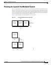
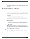
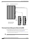
A diagram of the optical array cabling for a single-FCC multishelf systems is shown in Figure 3-2. In
this configuration:
• Each fabric card implements a single plane of the eight-plane switch fabric.
• The FCC contains all eight planes of the switch fabric.
For cabling instructions, see Cisco CRS-1 Carrier Routing System Multishelf System Interconnection
and Cabling Guide. For a list of items to consider as you plan the cable runs, see the “Fabric Cables”
section on page 3-16.
Switch Fabric Considerations
Consider the following as you plan the switch fabric configuration for your multishelf system:
• Review the “Switch Fabric Card Placement for High Availability” section on page 3-23 for
information about how to install fabric cards in the fabric card chassis to reduce the impact of a
double-fault power failure on switch fabric operation.
• Determine the number and lengths of fabric cables that are needed to connect S2 and S13 fabric
cards to each other.
• Determine how you will install the fabric cables between the fabric cards in the LCCs and FCCs. It
might also be useful to create a wiring diagram that shows the cable runs.
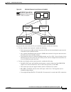
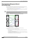
Figure 3-2 shows an example of how to connect the fabric cables between an FCC and two LCCs. The
figure shows the cabling for a single plane only; other fabric planes would be cabled in the same way.
In addition, note that only the top card cage of all chassis is shown. In a typical configuration, switch
fabric cards would also be installed in the lower card cage.
Note To ensure high availability of the switch fabric in the event of a power failure, be sure to install fabric
cards in the fabric card chassis according to the guidelines in the “Switch Fabric Card Placement for
High Availability” section on page 3-23.