


3-11
Cisco CRS-1 Carrier Routing System 16-Slot Multishelf System Site Planning Guide
OL-7422-04
Chapter 3 Multishelf System Planning
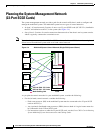
Planning the System Management Network (Cat6509)
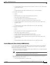
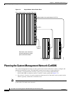
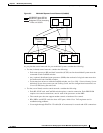
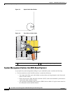
Figure 3-3 Multishelf System Control Network (Cat6509)
As you plan the control networks for your multishelf system, consider the following:
• For the (in-band) control network, consider the following:
–
Each route processor (RP) and shelf controller (SCGE) card in the multishelf system must be
connected to both Cat6509 switches.
–
Any (optional) distributed route processors (DRPs) that are head of a logical router must also
be connected to both Cat6509 switches.
–
For instructions on how to cable the Cat6509 switches, see Cisco CRS-1 Carrier Routing System
Multishelf System Interconnection and Cabling Guide, and for configuration instructions, see
Cisco IOS XR Getting Started Guide.
• For the (out-of-band) console control network, consider the following:
–
Each RP, SCGE card, and Cat6509 switch requires a console connection. Each DRP PLIM
requires two console connections, one for each of the processors on the DRP.
–
The console port does not support modem control or hardware flow control.
–
RPs, DRPs, and SCGE cards also have AUX ports, which Cisco TAC engineers use for
troubleshooting problems.
–
Use straight-through EIA/TIA-232 cable (RJ-45 connectors) for console and AUX connections.
RP0
GE0
DSC
GE1 GE0 GE1
RP1
SCGE0/RP0 plane GE link
SCGE1/RP1 plane GE link
Backplane FE link connecting
2 RPs or 2 SCGEs
Catalyst Switch 0
(External GE
Switch)
Catalyst Switch 1
(External GE
Switch)
138278
RP0
GE0
Rack 1
GE1
GE0 GE1
RP1
SCGE0
FCC
SCGE1
GE0 GE1 GE0 GE1