


5-14
Cisco uBR-3x10 RF Switch Hardware Installation and Cabling Guide
OL-1984-06
Chapter 5 Cabling the RF Switch With the Cisco uBR7246VXR CMTS
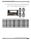
Connecting the Cables (Cisco uBR-MC16x Card)
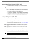
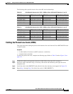
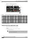
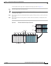
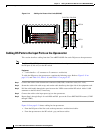
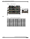
Figure 5-10 Output Cables (Gray and Brown)
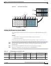
Cabling the Output Cables (CABLE PLANT to HUB)
This section describes cabling the RF switch for output.
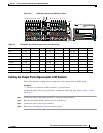
Equipment
• 16 cable bundles (MCX connector to F-connector—multicolor)
• 16 header blocks (installed)
Note Two more cable bundles may be required if you intend to route the upstream cables and the
downstream cables to different locations.
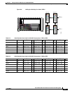
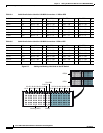
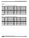
Table 5-10 Upconverter Output Cables (UPx1 and UPx2) to RF Switches (RFS-1 and RFS-2)
Color UPx RFS Ports Supports
D
UPx RFS Ports Supports
D
UPx RFS Ports Supports
D
Gray 1
1
1. Working 1 through 16 are located on UPx1
RFS-2–1F VXR1–LC1 9 RFS-2–3F VXR3–LC1 1
2
2. Protect 1 through 4 are located on UPx2
RFS-2–P2F VXR5–LC1
Brown 2 RFS-2–5F VXR1–LC2 10 RFS-2–7F VXR3–LC2 2 RFS-2–P1F VXR5–LC2
Gray 3 RFS-1–1F VXR1–LC3 11 RFS-1–3F VXR3–LC3 3 RFS-1–P2F VXR5–LC3
Brown 4 RFS-1–5F VXR1–LC4 12 RFS-1–7F VXR3–LC4 4 RFS-1–P1F VXR5–LC4
Gray 5 RFS-2–2F VXR2–LC1 13 RFS-2–4F VXR4–LC1
Brown 6 RFS-2–6F VXR2–LC2 14 RFS-2–8F VXR4–LC2
Gray 7 RFS-1–2F VXR2–LC3 15 RFS-1–4F VXR4–LC3
Brown 8 RFS-1–6F VXR2–LC4 16 RFS-1–8F VXR4–LC4
95743
UPx 2
UPx 1
12345678910111213141516