


CHAPTER
4-1
Cisco uBR-3x10 RF Switch Hardware Installation and Cabling Guide
OL-1984-06
4
Cabling the RF Switch With the Cisco uBR10012
CMTS Cable Interface Line Cards
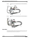
This chapter provides information about connecting cables between the Cisco uBR 3x10 RF Switch and
working and protect cable interface line cards in a Cisco uBR10012 CMTS.
This chapter contains the following sections:
• Protection Scheme for the Cisco uBR10012 CMTS, page 4-1
• RF Cable Assemblies, page 4-4
• RF Cable Assemblies for Cisco uBR10-MC5X20S/U/H Line Cards, page 4-6
• Installing the Header Blocks on the Cisco uBR 3x10 RF Switch, page 4-9
• Mapping the RF Cables from the Working and Protect Line Cards (MC16x, MC28C) to the
Cisco uBR 3x10 RF Switch, page 4-10
• Connecting the RF Cables (MC16x, MC28C Line Cards), page 4-15
• Mapping the Working and Protect Cisco uBR10-MC5X20S/U/H Line Cards RF Cables to the RF
Switch, page 4-21
• Connecting the RF Cables (Cisco uBR10-MC5X20S/U/H), page 4-26
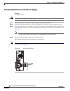
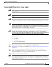
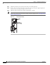
• Powering On the RF Switch, page 4-31
Protection Scheme for the Cisco uBR10012 CMTS
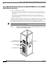
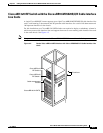
The N+1 redundancy protection scheme you select for your system depends largely on the number and
type of cable interface line cards you have installed in your Cisco uBR10012 router. The 7+1 eight-card
redundancy scheme supports redundancy among the cable interface line cards installed in a fully
populated Cisco uBR10012 router. Other redundancy schemes are designed to support partial cable
interface line card population in a Cisco uBR10012 router.
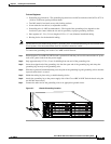
Note We recommend that the protect card be installed in slot 5/0 because this slot is directly below the
PROTECT section on the RF switch.