


4-18
Cisco uBR-3x10 RF Switch Hardware Installation and Cabling Guide
OL-1984-06
Chapter 4 Cabling the RF Switch With the Cisco uBR10012 CMTS Cable Interface Line Cards
Connecting the RF Cables (MC16x, MC28C Line Cards)
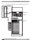
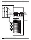
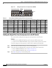
Figure 4-12 Cabling the Input Ports on the Upconverter (MC28C)
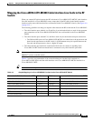
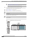
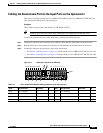
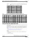
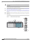
Cabling the Output Ports from the Upconverter to the RF Switch
This section describes cabling from the output ports on the upconverter to the RF switch.
Equipment
• 8 cables for Cisco uBR10-LCP2-MC16x cards (F-connector to MCX connector–gray)
• 16 cables for Cisco uBR10-LCP2-MC28C cards (F-connector to MCX connector–gray, brown)
To cable the output ports on the upconverter to the RF switch, complete the following steps.
Step 1 Connect the cable to the output connector (1–lower) on the upconverter.
Step 2 Connect the cable to the appropriate MCX connection on the CABLE PLANT header block.
• For Cisco uBR10-LCP2-MC16x cards, see Table 4-5 on page 4-19.
• For Cisco uBR10-LCP2-MC28C cards, see Table 4-6 on page 4-19.
Step 3 Repeat Step 1 through Step 2 for the remaining cables
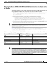
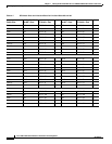
Table 4-4 Cisco uBR10-LCP2-MC28C Cabling (DS Ports to the Upconverter)
Color Line Card Slot DS Port UPx Conn D Color Line Card Slot DS Port UPx Conn D
Brown 8/0—working DS1 16 Brown 6/0—working DS1 8
Gray 8/0—working DS0 15 Gray 6/0—working DS0 7
Brown 8/1—working DS1 14 Brown 6/1—working DS1 6
Gray 8/1—working DS0 13 Gray 6/1—working DS0 5
Brown 7/0—working DS1 12 Brown 5/0—working DS1 4
Gray 7/0—working DS0 11 Gray 5/0—working DS0 3
Brown 7/1—working DS1 10 Brown 5/1—protect DS1 2
Gray 7/1—working DS0 9 Gray 5/1—protect DS0 1
103293
910111213141516 12345678
Input