


5-25
Cisco uBR-3x10 RF Switch Hardware Installation and Cabling Guide
OL-1984-06
Chapter 5 Cabling the RF Switch With the Cisco uBR7246VXR CMTS
Connecting the Cables (Cisco uBR-MC28x Line Card)
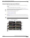
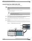
Cabling the Output Cables (CABLE PLANT to HUB)
The following section describes cabling the RF switch for output.
Note The output cables (CABLE PLANT) on the RF Switch are cabled in the reverse order of the input cables
(CMTS).
Equipment
• 16 cable bundles (MCX connector to F-connector—multicolor)
• 16 header blocks (installed)
Note Two more cable bundles may be required if you intend to route the upstream cables and the
downstream cables to different locations.
To cable the output to the cable plant, complete the following steps.
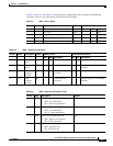
Step 1 Install the output cables in the header blocks. Start with the header block on the far right (1H—1A). For
easier troubleshooting, use the same color sequence that was used for CMTS cabling.
A–red, B–white, C–blue, D–green. H–yellow, I–violet, J–orange, K–black.
Step 2 Run the output cables (H–A) from header blocks to splitters, US laser receivers, or the low side of the
diplex filters
Step 3 Run the output cables (M–F) to the splitters and combiners, DS laser transmitters, or the high side of the
diplex filters.
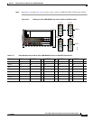
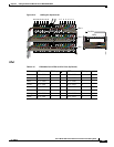
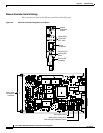
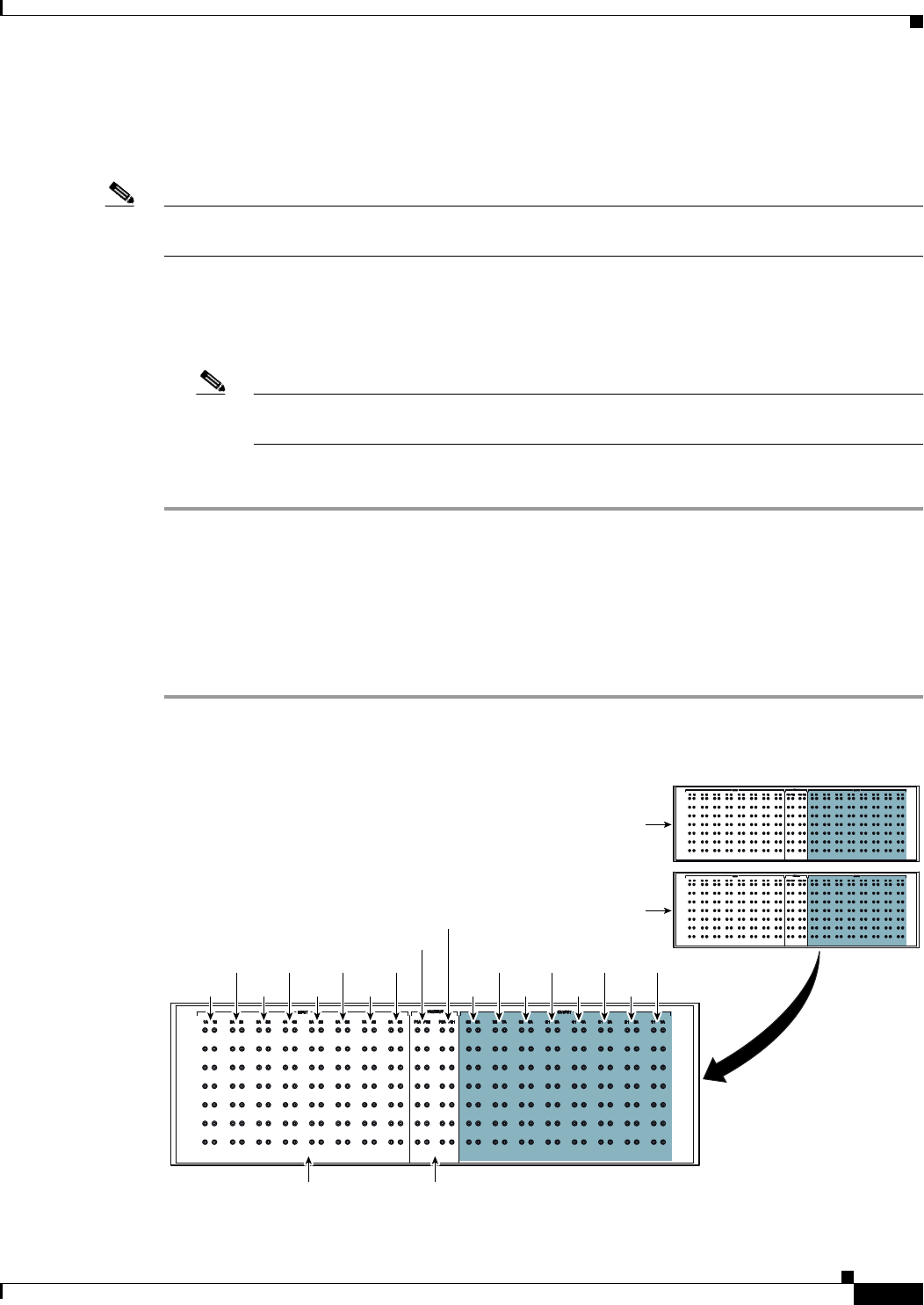
Figure 5-17 RF Switch Cable Plant Outputs (Turquoise)
103930
Working CMTS Protect
RFS-2
1A-1H
2A-2H
3A-3H
4A-4H
5A-5H
6A-6H
7A-7H
8A-8H
P1A-P1H
P2A-P2H
8H-8A
RFS-1
7H-7A
6H-6A
5H-5A
4H-4A
3H-3A
2H-2A
1H-1A